MyGate PQ81S Manual de usuario
ver.: 09_2021
Q81SQ81S
PROTECO S.r.l. Via Neive, 77 - 12050 Castagnito (CN) ITALY Tel. +39 0173 210111 - Fax +39 0173 210199 [email protected] - www.proteco.net
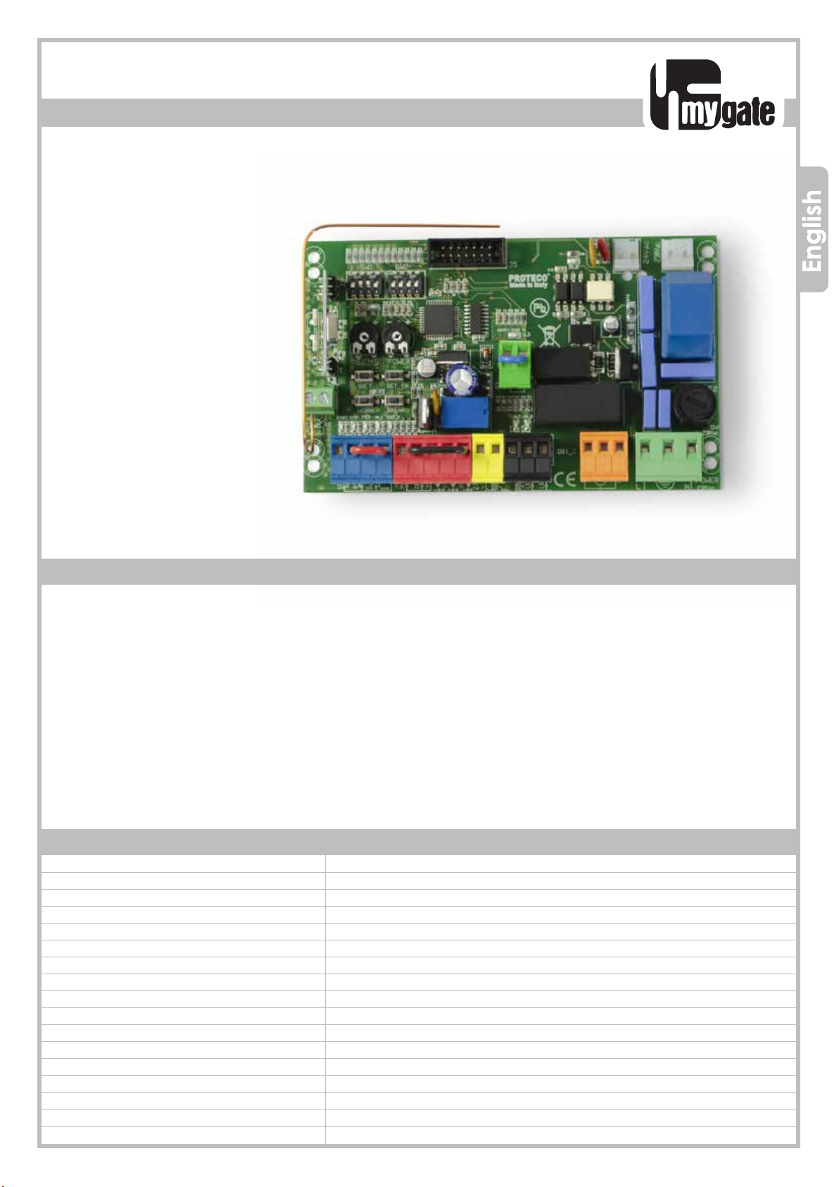
CONTROL PANEL FOR
SLIDING GATES
Control panel for 230V ac sliding gates operators
• Automatic programming mode with obstacle detection
• Sequential programming mode: adjustable force, slow down, working time per single motor
• Immediate closing
• Pedestrian opening
• Multi-occupation feature
• Second radio channel interface (optional)
• Output for electrolock connection
• Hammer action and lock pulse function
• Built-in radio receiver 433,92 MHz (32 codes) suitable for fixed or rolling code transmitters
• Input for 8K2 resistive safety edge
• Self diagnosis of malfunctions by LED coding
230V ac
TECHNICAL FEATURES
Instructions Manual
Item code PQ81S
Pcb’s dimensions 137 x 84 x 37 mm
Pcb’s weight 160 g
Main power supply 230V, 50-60Hz
Power supply tolerance -10% +20%
Transformer 230/21Vac – 15VA
Main fuse 5 A
Rated power 600 W
Max. power draw 3,5 A
Power draw in stand-by 30 mA
Blinker 24Vac, max 20 W
Accessories 24Vdc , max 5 W
Accessories -20 +50 °C
Protection rating IP55

PROTECO S.r.l. Via Neive, 77 - 12050 Castagnito (CN) ITALY Tel. +39 0173 210111 - Fax +39 0173 210199 [email protected] - www.proteco.net
Contents
1. SAFETY INSTRUCTIONS AND PRELIMINARY CHECKS ........................................................................................ pag. 01
2. DESCRIPTION AND MAIN COMPONENTS ......................................................................................................... pag. 02
3. ELECTRICAL CONNECTIONS .............................................................................................................................. pag. 03
3.1 LIMIT SWITCHES WIRING .......................................................................................................................... pag. 05
3.2 MAIN POWER ........................................................................................................................................... pag. 06
3.3 START DEVICES ......................................................................................................................................... pag. 06
3.3.1 TIMER
3.3.2 KEY-SWITCH
3.4 PEDESTRIAN OPENING ............................................................................................................................. pag. 06
3.5 EMERGENCY STOP BUTTON ..................................................................................................................... pag. 07
3.6 PHOTOCELLS ............................................................................................................................................. pag. 07
3.6.1 Photocells in CLOSING
3.6.2 Photocells in OPENING
3.7 SAFETY EDGE ............................................................................................................................................ pag. 08
3.7.1 Safety Edge in CLOSING
3.7.2 Safety Edge in OPENING
3.7.3 8K2 resistive safety edge in CLOSING ................................................................... pag. 11
3.7.4 8K2 resistive safety edge in OPENING
3.8 FLASHING LIGHT ....................................................................................................................................... pag. 10
3.9 HOV TO PLUG THE 2 RADIO CHANNEL JACK ..................................................................................... pag. 10
3.9.1 Auxiliary radio channel AUX
3.9.2 Signalling light
3.9.3 CCourtesy light
4. DEFAULT SETTINGS ............................................................................................................................................... pag. 11
5. BROWSING THE MENU
5.1 FUNCTIONS MENU
5.1.1 Automatic closing
5.1.2 8K2 RESISTIVE SAFETY EDGE INPUT (cut the power off)
6. OPERATION MODE ............................................................................................................................................ pag. 12
7. RADIO CODES .................................................................................................................................................... pag. 14
7.1 HOW TO DELETE EXISTING RADIO CODES
7.2 HOW TO STORE A RADIO CODE FOR START COMMAND
7.3 HOW TO STORE A RADIO CODE FOR PEDESTRIAN COMMAND
7.4 HOW TO STORE A RADIO CODE FOR THE 2° AUXILIARY RADIO CHANNEL
8. PROGRAMMING ................................................................................................................................................ pag. 15
8.1 AUTOMATIC mode
8.1.1 AUTOMATIC mode with OBSTACLE DETECTION
8.2 SEQUENTIAL mode .................................................................................................................................. pag. 16
8.2.1 SEQUENTIAL mode with OBSTACLE DETECTION
9. TROUBLE SHOOTING .......................................................................................................................................... pag. 17

Q81S_09_2021 1
PROTECO S.r.l. Via Neive, 77 - 12050 Castagnito (CN) ITALY Tel. +39 0173 210111 - Fax +39 0173 210199 [email protected] - www.proteco.net
1. SAFETY INSTRUCTIONS AND PRELIMINARY CHECKS
WARNING! Important instructions for the safety of people, READ CAREFULLY!
Save this manual for future consultation.
Do not allow children to play with the fixed command devices, or in the gate’s
area of operation.
Keep any remote control devices (i.e. transmitters) away from the children as
well
Children are forbidden to carry out cleaning and maintenance unless accom-
panied by adults.
Children over 8 years, persons with reduced physical, sensorial, mental capa-
bilities or unexperienced people are limited to use the operator unless accom-
panied by a supervisor or unless they get properly aware of potential hazards
associated.
Always cut the power off before operating.
Make sure the earth connection is duly wired.
Wiring, installation and functional tests must be carried out by expert qualified per-
sonnel in full compliance with current regulation EN12453.
Use of this control panel must be restricted to the transformer supplied by the Ma-
nufacturer.
A circuit breaker must be fitted close to the gate in compliance with the wiring
diagram and installation instructions (see paragraph 3).
Stay clear of the gate’s area of operation when in motion
Frequently check the system to see whetherany anomalies or signs of wear and
tear appear on the moving
parts, on the component parts, on the securing points, on the cables and any ac-
cessible connections.
If the system requires repairs or modifi cations, release the operator and do not use
it until safety conditions have been restored.

2 Q81S_09_2021
24Vac
230Vac
F2
J5
JP8 JP9
JP1
JP2 JP3
POWER
230Vac
5A
230Vac
DL1
- + - +
K4
K2
K3
FR1
21 22
SW1 SW2
DL2
START STOP PED
1 2 3 4 5 6 7 8 9 10 11 15 16 17 18 19 2012 13 14
V1
JP10
23 24
DL3
DL4 DL5 DL6 DL7 DL8
DL9 DL10
FR2
SENS POWER
SET SET TX
WORK BREAK
J1
SENS POWER
SET SET TX
WORK BREAK
PROTECO S.r.l. Via Neive, 77 - 12050 Castagnito (CN) ITALY Tel. +39 0173 210111 - Fax +39 0173 210199 [email protected] - www.proteco.net
2. DESCRIPTION AND MAIN COMPONENTS
J1 = radio receiver
J5 = input second radio channel jack
F2 = line fuse 230V 5A
FR1 = self resettable fuse 24V 1,6A
FR2 = self resettable fuse 24V 0,6A
V1 = varistor secondary
K1/K3 = motor relé
K4 = flashing light relé
TR2 = filter
JP1 = GREEN TERMINAL - aerial connection
JP2 = Secondary MOLEX card 24V ac
JP3 = Primary MOLEX card 230V ac
JP4 = BLUE TERMINAL – command devices
JP5 = RED TERMINAL - line and photocells
JP6 = YELLOW TERMINAL – flashing light
JP7 = BLACK TERMINAL - limit switch
JP8 = ORANGE TERMINAL - motor
JP9 = GREEN TERMINAL – line 230V / earth
JP10 = GREEN TERMINAL – safety edge (resistive or mechanical type) only in CLOSING
WARNING LED
DL1 = PROGRAMMING
DL2 = THRUST MOTOR
DL3 = SAFETY EDGE in CLOSING
DL4 = START
DL5 = STOP
DL6 = PEDESTRIAN START
DL7 = PHOTOCELL IN CLOSING
DL8 = PHOTOCELL IN OPENING
DL9 = LIMIT SWITCH in CLOSING
DL10 = LIMIT SWITCH in OPENING
PROGRAMMING BUTTONS

Q81S_09_2021 3
24Vac
230Vac
F2
J5
JP8 JP9
JP1
JP2 JP3
POWER
230Vac
5A
230Vac
DL1
- + - +
K4
K2
K3
FR1
21 22
SW1 SW2
DL2
START STOP PED
1 2 3 4 5 6 7 8 9 10 11 15 16 17 18 19 2012 13 14
V1
JP10
23 24
DL3
DL4 DL5 DL6 DL7
DL8 DL9 DL10
FR2
SENS POWER
SET SET TX
WORK BREAK
J1
M1
230V
N.C.
8K2
- + - +
TX RX - + - +
TX RX
PROTECO S.r.l. Via Neive, 77 - 12050 Castagnito (CN) ITALY Tel. +39 0173 210111 - Fax +39 0173 210199 [email protected] - www.proteco.net
PHASE
NEUTRAL
EARTH
CLOSE
CAPACITOR
FLASHING LIGTH
24V ac MAX 20w
PEDESTRIAN
STOP
START
NEUTRAL
CLOSING
PHOTOCELLS
OPENING
PHOTOCELLS
PHOTOCELLS IN CLOSING
PHOTOCELLS IN OPENING
-24V RX
+24V TX/RX
TRANSFORMER
230V / 21V
RED
RED
BLACK
BLACK
WIRING Diagram for 230Vac OPERATORS
-24V TX
3. ELECTRICAL CONNECTIONS
CIRCUIT
BREAKER
OPEN
NEUTRAL
NEUTRAL
FC CLOSING
FC OPENING
THE CONTROL UNIT COMES FROM MANUFACTURER
PRE-WIRED AS FOLLOWS
N.B.:
ALL SAFETY DEVICES MUST BE CONNECTED BEFORE STARTING
PROGRAMMING, OTHERWISE THE CONTROL PANEL SHALL
JP6
FLASH
24V ac
JP8
M1
PED
J5
JP1
22
21
JP2
JP3
JP4
START
STOP
PED
JP5
RX -24V
TX - RX +24V
Test Photo TX -24
FOTO
FTAP
JP9
FN
4 Q81S_09_2021
JP7
PROTECO S.r.l. Via Neive, 77 - 12050 Castagnito (CN) ITALY Tel. +39 0173 210111 - Fax +39 0173 210199 [email protected] - www.proteco.net
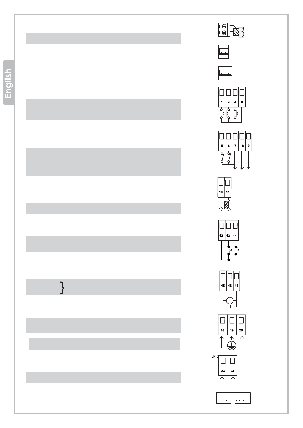
JP1 = GREEN TERMINAL -Aerial connection
21 signal wire
22 earth wire
JP2 = RED WIRES - secondary MOLEX card 24V dc
JP3 = BLACK WIRES - primary MOLEX card 230V ac
JP4 = BLUE TERMINAL – command devices
1 START (N.O. contact)
2 STOP (N.C. contact)
3 PEDESTRIAN (N.O. contact)
4 NEUTRAL
JP5 = RED TERMINAL – line and photocells
5 photocell in closing (N.C. contact)
6 photocell in opening (N.C. contact)
7 RX photocells -24V
8 TX/RX +24V
9 TX photocells -24V
JP6 = YELLOW TERMINAL – flashing light
10 flashing light 24V ac - max 20W
11 flashing light 24V ac - max 20W
JP7 = BLACK TERMINAL – LIMIT SWITCH
12 neutral
13 limit switch in closing
14 limit switch in opening
JP8 = ORANGE TERMINAL - MOTOR
15 OPEN
16 NEUTRAL MOTOR OUTPUT
17 CLOSE
JP9 = GREEN TERMINAL - line 230V + earth
18 LINE
19 EARTH
20 NEUTRAL
Make sure a circuit breaker is properly fitted
to the gate electric box.
JP10 = GREEN TERMINAL – safety edge
23 safety edge in CLOSING
24 safety edge in CLOSING
J5 = input second radio channel jack
OPEN
CLOSE
FC OPENING
FC CLOSING
NEUTRAL

Q81S_09_2021 5
PROTECO S.r.l. Via Neive, 77 - 12050 Castagnito (CN) ITALY Tel. +39 0173 210111 - Fax +39 0173 210199 [email protected] - www.proteco.net
Il the motor is positioned on the left,
switch SW2 dip no.1 = ON
(the limit switch turns automatically.
No connections are needed)
Il the motor is positioned on the left,
switch SW2 dip no.1 = ON
(the limit switch turns automatically.
No connections are needed)
JP8
Brown
Whit
3.1 MOTORS wiring
Please check motor wirings according to the gate opening direction
Gate opening from left to RIGHT (viw from inside courtyard)
FCOPEN
NEUTRAL
FCCLOSING
Gate opening from right to LEFT (view from isnide property)
The control unit is pre-set for gate opening
from left to right (looking from inside the
courtyard as shown in the drawing).
OUTSIDE
INSIDE
OUTSIDE
INSIDE
Right
gear motor
Left
gear motor
34
JP7
BROWN
BLACK
BLUE- COMMON
MECHANICAL
LIMIT SWITCH
MAGNETIC
LIMIT SWITCH
34
JP7
BLACK

JP4 JP5 JP6
JP4 JP5 JP6
JP4 JP5 JP6
JP4 JP5 JP6
JP9
230V
6 Q81S_09_2021
PROTECO S.r.l. Via Neive, 77 - 12050 Castagnito (CN) ITALY Tel. +39 0173 210111 - Fax +39 0173 210199 [email protected] - www.proteco.net
3.3 START DEVICES
Wire the START contact (N.O. contact) to 1 – 4, terminal JP4.
An additional START contact can be wired in PARALLEL (N.O. contact)
3.4 PEDESTRIAN OPENING
Wire the PEDESTRIAN START (N.O. contact) to 3-4, terminal JP4.
An additional PEDESTRIAN START contact can be wired in PARALLEL
(N.O. contact).
OROLOGIO
3.3.2 KEY SWITCH
Wire the KEY SWITCH (N.O. contact) to 1-4, terminal JP4.
3.2 MAIN POWER
The main line must be protected by a proper CIRCUIT BREAKER.
Connect the line 230V to 18-19-20, terminal JP9, fulfilling the
polarity (18 PHASE – 19 EARTH – 20 NEUTRAL)
CIRCUIT
BREAKER
PHASE
NEUTRAL
PEDESTRIAN
START
3.3.1 TIMER
It is possible to wire a TIMER (N.O. contact) to 1-4, terminal JP4.
ATTENTION!:
when connecting a TIMER, the multi-users function
must be enabled. SW1 DIP 2 = ON

Q81S_09_2021 7
JP4 JP5 JP6
JP4 JP5 JP6
TR AS
+
+AC
-AC
TX
+
-
RX
+AC -AC
24
12Vdc
24Vac
24Vdc
12Vdc
24Vdc
24Vca
JP4 JP5 JP6
PROTECO S.r.l. Via Neive, 77 - 12050 Castagnito (CN) ITALY Tel. +39 0173 210111 - Fax +39 0173 210199 [email protected] - www.proteco.net
3.6 PHOTOCELLS
3.6.1 Photocells IN CLOSING
Feed the photocells through 7-8-9, terminal JP5.
Wire the photocell contact (N.C. contact) to 5-7, terminal JP5.
An additional photocell set can be wired in SERIES (N.C. contact).
- If the photocell beam is broken during CLOSING,
the gate stops and reverses after 1,5 sec.
- If the photocell beam is broken during OPENING,
the gate keeps on working normally.
The PHOTOCELLS IN CLOSING are important for
the safety of people and objects.
N.B.: To desable the photocell in closing
during installation, plug 5 and 9 together.
3.6.2 Photocells in OPENING
Feed the photocells through 7-8-9, terminal JP5.
Wire the photocell contact (N.C. contact) to 6-7, terminal JP5.
An additional photocell set can be wired in SERIES (N.C.
contact).
- If the photocell beam is broken during OPENING, the gate
stops and reverses for 3 sec
The PHOTOCELLS IN OPENING are important for the safety of
people and objects..
N.B.: Before wiring any PHOTOCELL in OPENING, remove the
jumper between terminal 6 and terminal 9.
EMERGENCY
STOP BUTTON
3.5 EMERGENCY STOP BUTTON
Wire the STOP BUTTON (N.C. contact) to 2-4, terminal JP4.
An additional STOP BUTTON contact can be wired in SERIES (N.C. contact)
The EMERGENCY STOP BUTTON is important for the safety
of people and objects
N.B.: Before wiring any STOP contact remove the jumper between
terminal 2 and terminal 4.
PLUG 5 - 9

8Q81S_09_2021
JP10
N.C.
JP4 JP5 JP6
N.C.N.C.
TR AS
+
+AC
-AC
TX
+
-
RX
+AC -AC
24
12Vdc
24Vac
24Vdc
12Vdc
24Vdc
24Vca
N.C.
TR AS
+
+AC
-AC
TX
+
-
RX
+AC -AC
24
12Vdc
24Vac
24Vdc
12Vdc
24Vdc
24Vca
N.C.
PROTECO S.r.l. Via Neive, 77 - 12050 Castagnito (CN) ITALY Tel. +39 0173 210111 - Fax +39 0173 210199 [email protected] - www.proteco.net
3.7 SAFETY EDGE
3.7.1 Mechanical safety edge in CLOSING
Wire the safety edge to 23 - 24, terminal JP10.
•If the contact is broken during CLOSING, the
gate stops and reverses.
•If the contact is broken during OPENING, the
gate keeps on working normally
Mechanical safety edge + photocells in CLOSING
Wire the safety edge and the N.C. contact of the
photocell in series.
•If the contact is broken during CLOSING, the gate
stops and reverses.
•If the contact is broken during OPENING, the gate
keeps on working normally.
3.7.2 Mechanical safety edge in OPENING
Wire the safety edge to 6 – 9, terminal JP5.
•If the contact is broken during OPENING,
he gate stops and reverses after 3 sec.
•If the contact is broken during CLOSING,
the gate keeps on working normally.
Mechanical safety edge + photocells in OPENING
Wire the safety edge and the N.C. contact of t
he photocell in series.
•If the contact is broken during OPENING, the gate
stops and reverses after 3 sec.
•If the contact is broken during CLOSING, the gate
keeps on working normally.
N.B.: Before wiring any SAFETY STRIP in
CLOSING, remove the jumper
between terminal 23 and
terminal 24.
Tabla de contenidos
Otros manuales de Panel de control de MyGate


