Moeller SmartWire Guía del usuario

SmartWire Startup Guide V1.02
SmartWire Startup Guide V1.02
© by Moeller GmbH 1 / 42

SmartWire Startup Guide V1.02
The document can be found under the following path:
ftp://ftp.moeller.net/SMARTWIRE/ENGLISH/01_PRODUCT/08_STARTUP_GUIDE
{ DOWNLOAD }
All rights, including those of translation, reserved. No part of this manual may be
reproduced, stored in a retrieval system, or transmitted in any form or by any means,
electronic, mechanical, photocopying, micro-filming, recording or otherwise, without
the prior written permission of Moeller GmbH, Bonn.
Changes:
V1.0 ÆV1.01 Moeller logo updated
V1.01 ÆV1.02 Screenshots updated
© by Moeller GmbH 2 / 42

SmartWire Startup Guide V1.02
Contents
1Introduction...................................................................................................... 4
2System components for motor starters with SmartWire.............................. 5
3Connections on the motor starter .................................................................. 7
4Assembling a motor starter row..................................................................... 8
5Electrically commissioning SmartWire........................................................ 10
6SmartWire integration for XC100/200 via Profibus DP................................ 12
6.1 PLC connection.............................................................................................................12
6.2 Installing the GSD file ...................................................................................................13
6.3 Creating a program in easySoft CoDeSys....................................................................14
6.4 Setting for Profibus node monitoring.............................................................................21
6.5 Diagnostics ...................................................................................................................22
6.5.1 XC100/200 system diagnostics................................................................................................... 22
6.5.2 Profibus DP diagnostics.............................................................................................................. 24
6.6 Example program for XC200 (SWIRE-XC200-ProfibusDP.pro)....................................27
7SmartWire integration for XC100/200 via CANopen.................................... 28
7.1 PLC connection.............................................................................................................28
7.2 Installing the EDS file....................................................................................................29
7.3 Creating a program in easySoft CoDeSys....................................................................29
7.4 Settings for CANopen node monitoring with Node guarding.........................................33
7.5 Settings for the CANopen Heartbeat node monitoring..................................................34
7.6 CANopen slave monitoring ...........................................................................................35
7.7 Example program for XC200 (SWIRE-XC200-CANopen.pro)......................................39
8SmartWire integration for easy800 via easyNET......................................... 40
9SmartWire integration for ECP4 via CANopen ............................................ 40
10 SmartWire integration for S7-300 via Profibus DP...................................... 40
© by Moeller GmbH 3 / 42

SmartWire Startup Guide V1.02
1 Introduction
SmartWire enables switching devices to be connected to a PLC without the need for
any complex control circuit wiring. The control wiring between the PLC and the
switchgear is replaced by the plug-in SmartWire module and pre-assembled
connection cables. The wiring requirement is drastically reduced and thus makes
wiring errors a thing of the past. This saves time and money during mounting,
commissioning and troubleshooting during operation.
SmartWire is an addition to the well-established range of Moeller switchgear and is
designed to be an accessory for standard devices. The flexibility of the switchgear is
fully retained since all known system accessories can still be used. The use of
standard devices reduces the stock-keeping costs required and ensures the
worldwide availability of replacement parts.
© by Moeller GmbH 4 / 42

SmartWire Startup Guide V1.02
2 System components for motor starters with SmartWire
(4)
(6)
(1)
(5) (2)
(3)
The following pages describe the setup, configuration and function of the SmartWire
system using eight Moeller motor starters with the "SWIRE-DIL" SmartWire module
for DILM contactors.
The motor starters presented here consist of 5 components:
1) PKZM motor-protective circuit-breaker
2) Connection element
3) DILM contactor
4) Tool-less plug connector
5) SmartWire module for DILM "SWIRE-DIL"
6) SmartWire connection cable "SWIRE-CAB-xxx"
© by Moeller GmbH 5 / 42

SmartWire Startup Guide V1.02
A motor starter is assembled simply from these 5 components.
Before fitting the SWIRE-DIL to the corresponding contactor, it must be ensured that
the position of the terminal pin is set correctly.
DILM contactor size 1 DILM contactor size 2
© by Moeller GmbH 6 / 42

SmartWire Startup Guide V1.02
3 Connections on the motor starter
L1 L2 L3
M
Wiring for motor
feeder
(AC load circuit)
Incomer wiring
(AC load circuit)
X1/X2 optional wiring
NHI (auxiliary contact
for PKZM)
X3/X4 for opening
the contactor control circuit
(Jumpered as standard)
The SWIRE-DIL has 4 screw terminals, X1/X2 and X3/X4.
X1/X2 is provided with a digital input for isolated contacts. This input is designed for
connecting the NHI auxiliary contact of the PKZ and thus indicates the status of the
PKZ (off/tripped and on) to the SWIRE-DIL.
A jumper (fitted as standard) at X3/X4 closes the control circuit for the contactor.
Opening the connection at X3/X4 makes it possible to interrupt the circuit for the
contactor (independently of the SWIRE-DIL control logic). X3/X4 enables, for
example, the electrical interlock of the contactor for a reversing starter combination.
© by Moeller GmbH 7 / 42

SmartWire Startup Guide V1.02
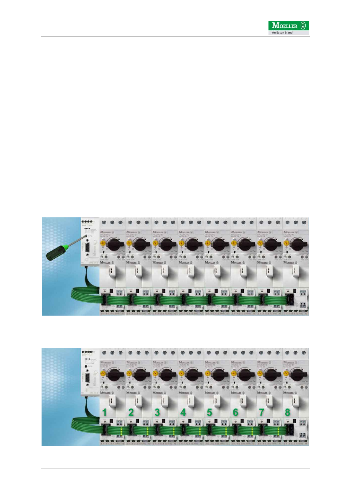
4 Assembling a motor starter row
The assembly of the system couldn't be easier. The motor starters are firstly fitted in
succession onto the mounting rail. The NHI may have been installed on the PKZ
beforehand and the connection cables connected to the terminal X1/X2.
All SWIRE-DILs are then interconnected using the SmartWire connection cables. The
SWIRE-CAB-008 is recommended for connecting two starters with (DILM7…11
contactors). If adjacent contactors are not identical, e.g. DILM9 next to DILM15 or
vice versa, the next larger connection cable SWIRE-CAB-011 is recommended.
© by Moeller GmbH 8 / 42

SmartWire Startup Guide V1.02
© by Moeller GmbH 9 / 42
The next step involves the installation of the fieldbus gateway. The following
interfaces are possible at present:
1) SWIRE-GW-DP Æfor connecting to Profibus DP V0
2) easy223-SWIRE ÆCANopen mode: for connecting to a CANopen master
3) easy223-SWIRE ÆeasyNET mode: for connecting to an easyNET for easy800
Ideally, the fieldbus gateway is positioned approx. 10 mm away from the first starter.
SWIRE-CAB-015 is recommended as the SmartWire cable.
The gateway requires two operating voltages:
a) UInterface : used for supplying the gateway and the SmartWire modules.
b) UAux : supply voltage here for the contactors on the motor starter
ATTENTION!
The power supply must be provided with appropriate fuse protection.
a) UInterface : 1A fuse
b) UAux : 3A fuse
Further information on this is provided in the technical descriptions (AWBs) of the
SmartWire components.
24VDC power
supply
for SWIRE devices
24VDC incomer
for DILM contactors
Distance from gateway to
the first starter, ideally
approx. 10mm
SmartWire Startup Guide V1.02
5 Electrically commissioning SmartWire
The SmartWire system which is connected to the higher-level PLC via the fieldbus
gateway in place can be configured independently of the controlling PLC and
commissioned.
After the power supply is switched on, the SmartWire gateway always checks the
connected SmartWire modules and compares this with the internally stored
configuration. The SmartWire gateway is factory set without a reference
configuration. In other words, it does not expect to find any modules.
In this example with 8 motor starters and thus also SmartWire modules, the
SmartWire gateway will detect the deviation when the first module is checked. This is
indicated by the regular flashing of the SmartWire LED on the gateway and on the
first SWIRE-DIL. The LEDs of SWIRE-DILs 2-7 flash in pulses.
This means that they are in operation but have not yet been accessed by the
gateway, since the first module does not match the reference configuration in the
SmartWire gateway.
The currently connected configuration can be transferred by pressing the
configuration button on the gateway. This must be held down > 1 second. If this time
is exceeded, the Ready LED will change from slow to fast flashing and will thus
indicate that the configuration process has been initiated. The configuration button
can then be released.
The gateway then carries out an automatic configuration so that all stations are
addressed in turn (in this case 1-8).
© by Moeller GmbH 10 / 42
Tabla de contenidos
Otros manuales de Sistema de control de Moeller


