Mitsubishi Electric HD-6000 Manual de usuario

CAUTION:
Before servicing this chassis, it is important that the service person read the "SAFETY PRECAUTIONS" and
"PRODUCTSAFETYNOTICE"containedinthismanual.
• Design specifications are subject to change without notice.
MITSUBISHI DIGITAL ELECTRONICS AMERICA, INC.
9351JeronimoRoad,Irvine,CA 92618-1904
Copyright © 2005 Mitsubishi Digital ElectronicsAmerica, Inc.
AllRights Reserved
MITSUBISHIELECTRIC
SerSer
SerSer
Servicevice
vicevice
vice
ManualManual
ManualManual
Manual
20052005
20052005
2005
SET TOP BOX
V26S CHASSIS
SPECIFICATIONS
• Power Input : AC 120V, 60Hz
•Power Usage : 82W
• Frequency Range : VHF 54 ~ 470MHz
UHF 470 ~ 806MHz
Analog Cable - 1 ~ 125
Digital Cable - 1 ~ 135
•Antenna Input : 2 RF 75Ω unbalanced
• Tuning : 1NTSC/ATSC/QAM
1 CableCARD™ Slot
1 NTSC for PIP
• Cabinet Dimensions : 17"(W) x 3.4"(H) x 16.8"(D)
• Weight : 27 lbs
• PVR : 120 GB Hard Disc
Approx. 12 hrs HD Recording
72 hrs SD Recording
• Analog Input : VIDEOIN JACK (RCAType)
Levels 1.0Vp-p 75Ω unbalanced
: AUDIOINJACK (RCAType)
-4.7dBm 43kΩunbalanced
: S-VIDEOINJACK
(Y/C separate type)
Y:1.0 Vp-p C:0.286Vp-p(BURST)
75Ω unbalanced
: COMP/Y, Cr,Cb (RCAType)
Y: 1.0 Vp-p Cr, Cb: 700mVp-p
: ATV/Y(G),Pr(R),Pb(B),H, V
Y: 1.0Vp-p with sync 75Ω (BNC)
Pr, Pb: 700mV 75Ω
H, V: 3.0Vp-p 75Ω
:VGA/R,G,B,V,H(15 pin D)
• Output Level : VIDEOOUTJACK (RCAType)
1.0Vp-p 75Ω unbalanced
: COMP/Y,Cr,Cb
Y: 1.0 Vp-p Cr, Cb: 700mVp-p
: AUDIOOUT JACK (RCAType)
-4.7dBm 4.7kΩ unbalanced
• Digital : IEEE-1394 I/O Jacks
Interface : AC-3 Digtal Audio Output
: HDMI™ Input/Output
: MonitorLinkTM Control/RS-232C
: CableCARD™ Slot
: NetCommand®
.
MODEL
HD-6000


MODEL: HD-6000
Page 3
INTRODUCTION ................................................................................................................................5
PRODUCTSAFETYNOTICE ............................................................................................................. 5
SAFETYPRECAUTIONS ...................................................................................................................6
PWB-LOCATIONS .............................................................................................................................7
DISASSEMBLY ..................................................................................................................................7
DisassemblyProcedures Sequence ...................................................................................... 7
TopCoverremoval ..................................................................................................................8
HDD(HardDrive)removal .......................................................................................................9
PWB’Sremoval ................................................................................................................... 10
ELECTRICALADJUSTMENTS ........................................................................................................ 11
Equipment .................................................................................................................................... 11
Option Menu / Initialization Defaults /AV Defaults ......................................................................... 12
LED Diagnostics ........................................................................................................................... 13
RemoteControl OperationalMode ................................................................................................ 13
CircuitAdjustment Mode ............................................................................................................... 14
Transferingdata ............................................................................................................................ 15
Adjustment Items List................................................................................................................... 15
AdjustmentProcedures ................................................................................................................ 16
Test Points .......................................................................................................................... 16
Main-YGain......................................................................................................................... 16
Sub-YGain .......................................................................................................................... 17
SubPictureOffset ............................................................................................................... 17
CHIPPARTS REPLACEMENT ......................................................................................................... 18
REPLACEMENTPARTS .................................................................................................................. 19
PartsOrdering .............................................................................................................................. 19
CriticalandWarranty Parts Designation........................................................................................ 19
PartsTolerance Codes.................................................................................................................. 19
SERVICE PARTS LIST .................................................................................................................... 20
CIRCUITRYBLOCK DIAGRAMS ..................................................................................................... 29
StandbyPowerSupplies ............................................................................................................... 29
PWB-DM PowerSupplies ............................................................................................................. 30
PWB-SIGNALSwitchedPowerSupplies ...................................................................................... 30
Video Select Circuitry ................................................................................................................... 31
VideoOutputCircuitry................................................................................................................... 32
Sync Signal Selection................................................................................................................... 33
Sync Signal Output Path .............................................................................................................. 34
RecordSignalPath....................................................................................................................... 34
SoundSignalPath ........................................................................................................................ 35
Control Circuitry ............................................................................................................................ 36
CommandInput Circuitry............................................................................................................... 37
MacrovisionDetection ................................................................................................................... 37
PWB-DM Signal Path ................................................................................................................... 38
CONTENTS

Page 4
MODEL: HD-6000
Part 2
Schematic Diagrams
CONTENTS Page
SCHEMATICDIAGRAMS
OverallPWB Interconnect Diagram .................................................................................................1
POWER / E2P / CONTROL / MV Decoder] ....................................................................................2
TERMINAL-1/ TERMINAL-2 [Inputs / Outputs] ...............................................................................3
SIGNAL-1[VideoSwitch]................................................................................................................4
SIGNAL-2[Decoder/Switch]..........................................................................................................5
SIGNALS-3[Micro} .........................................................................................................................6
SIGNAL-4[TVGO] ..........................................................................................................................7
SIGNAL-5[MPEGEncoder]............................................................................................................8
SIGNAL-6[HDMIRX] ...................................................................................................................... 9
SIGNAL-7[HDMITX]..................................................................................................................... 10
SIGNAL-8[Video Output]............................................................................................................. 11
SIGNAL-9[IR232] ......................................................................................................................... 12
TUNER-1[ATSC/NTSCTuner] .................................................................................................... 13
TUNER-2[MainATSC/ NTSC Demodulators] ............................................................................... 14
PWB LAYOUT DIAGRAMS .............................................................................................................. 15

MODELS: HD-6000
Page 5
INTRODUCTION
Thisservice manual providesservice instructions for STBmodel HD-6000which usesthe V26Schassis. Service
personnelshould read this manualthoroughly before servicingthese chassis.
Thisservice manual includes:
1. SafetyPrecautions
2. Assembly and disassembly instructions.
3. Servicingprinted circuit boards (PCBs).
4. Electrical adjustments.
5. Chipparts replacement procedures.
6. Circuitpathdiagrams.
The parts list section of this service manual includes:
1. Cabinetand screen parts.
2. Electrical parts.
Schematicand block diagramsof theabove listedmodels areincluded inthis servicemanual forbetter understanding
of the circuitry. PCB drawings are also included for easy location of parts and test points.
PRODUCT SAFETY NOTICE
Manyelectrical and mechanicalparts intelevision receivershave specialsafety relatedcharacteristics. These charac-
teristics are often not evident from visual inspection nor can the protection afforded by them necessarily be obtained by
usingreplacement components rated for highervoltage, wattage, etc.
Replacementparts which havespecial safetycharacteristics areidentified inthis servicemanual.
Electrical components having such features are identified by shading on the schematic diagrams and by bold type in
the parts list of this service manual. and by marking on the supplementary sheet for this chassis to be issued subse-
quently. The replacement for any safety part should be identical in value and characteristics.

Page 6
MODELS: HD-6000
SAFETY PRECAUTIONS
NOTICE: Observe all cautions and safety related notes located inside the receiver cabinet and on the
receiverchassis.
WARNING:
1. Operationof this receiver outside thecabinet or with the coverremoved presents a shock hazard
fromthe receiver's power supplies. Workon the receivershould notbe attempted byanyone whois
notthoroughlyfamiliarwiththeprecautions necessary when working on high voltage equipment.
2. Whenservice is required, observethe original lead dress.Extra precaution shouldbe taken to
assure correct lead dress in the high voltage area. Where a short-circuit has occurred, replace those
componentsthat indicate evidence of overheating.
Leakage current check
Before returning the receiver to the customer, it is recommended that leakage current be measured according to the
followingmethods.
1. Cold Check
With the alternating current (AC) plug removed from the AC source, place a jumper across the two AC plug
prongs. Connect one lead of an ohm meter to the AC plug and touch the other lead to each exposed metal part
(i.e. antennas, handle bracket, metal cabinet, screw heads, metal overlay, control shafts, etc.), particularly any
exposed metal part that has a return path to the chassis. The resistance of the exposed metal parts having a
return path to the chassis should be a minimum of 1Mega Ohm. Any resistance below this value indicates an
abnormalcondition and requires corrective action.
2. Hot Check ...Use the circuit shown below to perform the hot check test.
1. Keep switch S1 open and connect the receiver to the measuring circuit. Immediately after
connection,andwith the switching devices ofthe receiver in theiroperating positions, measure
the leakage current for both positions of switch S2.
2. Close switch S1, energizing the receiver. Immediately after closing switch S1, and with the
switchingdevicesofthe receiver in their operating positions, measurethe leakage current for both
positions of switch S2. Repeat the current measurements of items 1 and 2 after the receiver has
reached thermal stabilization. The leakage current must not exceed 0.5 milliampere (mA).
MODELS: HD-6000
Page 7
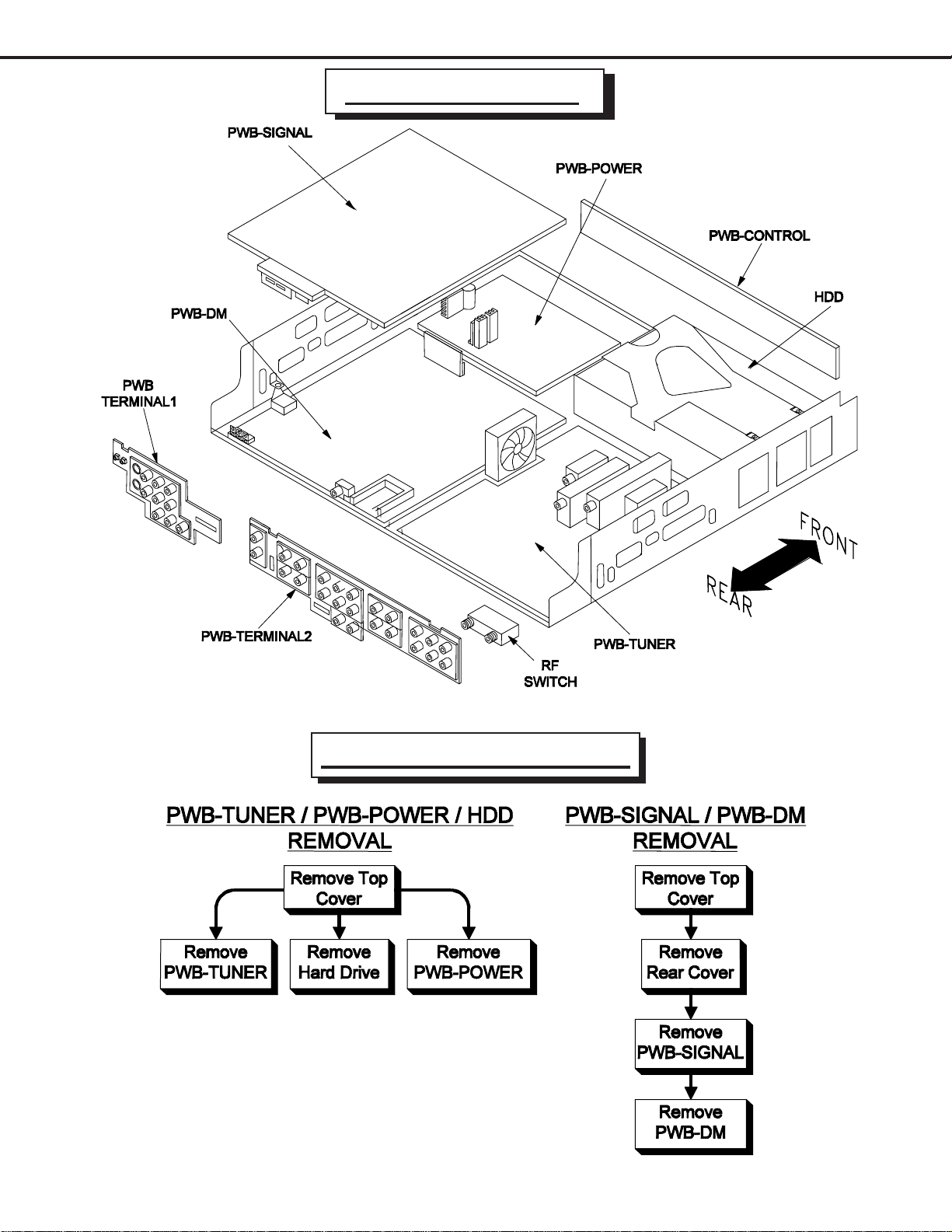
PWB LOCATIONS
Disassembly Sequence

Page 8
MODELS: HD-6000
TOP COVER REMOVAL

MODELS: HD-6000
Page 9
HDD (Hard Drive) Removal
NOTE: Prior to HDD replacement, perform the prodedure
“Replacing the HDD” described on page 15.

Page 10
MODELS: HD-6000
PWB Removal
Otros manuales para HD-6000
1
Tabla de contenidos


