Mitsubishi Electric DD-5000 Manual de usuario

MITSUBISHI DIGITAL ELECTRONICS AMERICA, INC.
9351 Jeronimo Rd. Irvine, CA 92618
Copyright © 2000 Mitsubishi Digital Electronics America, Inc.
All Rights Reserved
Operating conditions: Temperature: 5 °C to 35°C
Operation status: Horizontal
Video output: 1.0 V (p-p), 75Ω, negative
sync., pin jack x 1
S Video output: (Y) 1.0 V (p-p), 75Ω, nega-
tive sync., Mini DIN 4-pin x 1
(C) 0.286 V (p-p), 75Ω
Color Difference output: (Y) 1.0 V (p-p), 75Ω, nega-
tive sync., pin jack x 1
(Cr)/(Cb) 0.7 V (p-p), 75Ω, pin
jack x 2
Digital Audio output: (Bitstream/PCM) 0.5 V (p-p),
75Ω, pin jack x 1,
Optical connector x 1
Analog Audio output: 2.0 V (rms), 330Ω, pin jack
2 CH L R x 2,
5.1 CH SURROUND x 6
CAUTION
Before servicing this chassis, it is important that the service person reads all SAFETY PRECAUTIONS and the
SAFETY NOTICE in this manual.
SPECIFICATIONS
Power Supply: 120V AC, 60 Hz
Power Consumption: 19W
Weight: 6.7 lb.
External Dimensions: 17"x 3-1/4"x12-1/4"
(W/H/D)
Signal System: Standard NTSC
Laser: Semiconductor laser,
wavelength 650 nm
Frequency Range: (Digital Audio)
Audio CD: 4 Hz to 20 kHz
DVD Linear -
48 kHZ Sampling: 4 Hz to 22 kHz
96 kHZ Sampling: 4 Hz to 44 kHz
Signal-To-Noise Ratio: More than 112 dB (EIAJ)
Audio Dynamic Range: More than 106 dB (EIAJ)
Harmonic Distortion: Less than 0.001%
Wow and flutter: Below measurable level
(less than ± 0.001%
(W.PEAK)) (EIAJ)
SerSer
SerSer
Servicevice
vicevice
vice
ManualManual
ManualManual
Manual
2000
MITSUBISH ELECTRIC
Model
DD-5000
DVD Player
OPEN/CLOSE
STOP PLAY PAUSE/STEP
POWER
DD-5000
STANDBY
SKIP
REV FWD
/
CDVD
TITLE TRK CHP TOTAL REMAIN MEMORY
HDCD

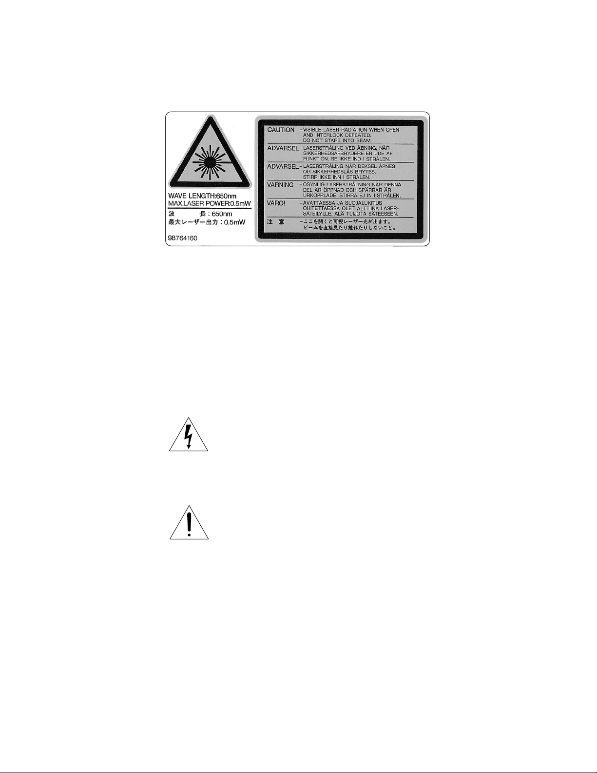
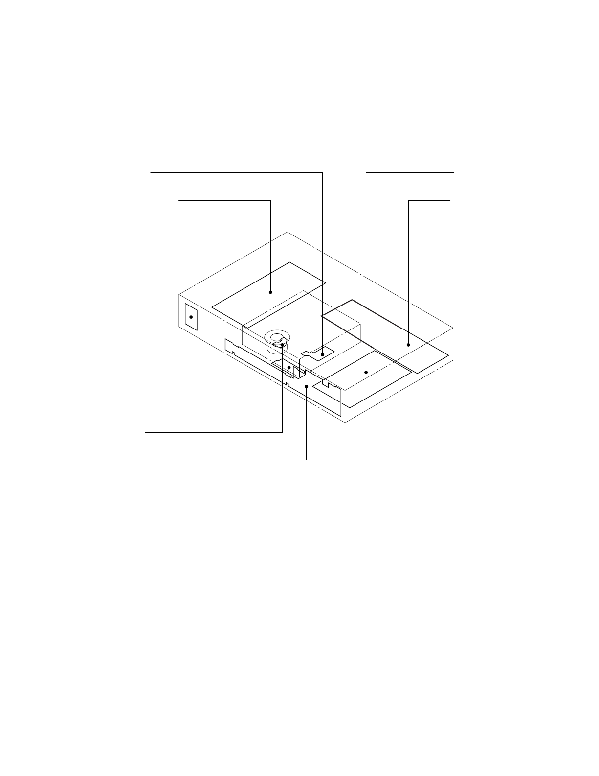
LASER BEAM CAUTION LABEL
When the power supply is on, do not remove this laser caution label. If it is removed, laser radiation may be recceived.
The lightning flash with arrowhead symbol, within an
equilateral triangle, is intended to alert the user to the
presence of uninsulated “dangerous voltage” within the
product’s enclosure that may be of sufficient magnitude to
constitute a risk of electric shock to persons.
The exclamation point within an equilateral triangle is
intended to alert the user to the presence of important
operating and maintenance (servicing) instructions in the
literature accompanying the appliance.
SAFETY NOTICE

SAFETY PRECAUTIONS
LEAKAGE CURRENT CHECK
Plug the AC line cord directly into a 120V AC outlet (do
not use an isolation transformer for this check). Use an
AC voltmeter, having 5000 Ωper volt or more sensitivity.
Connect a 1500 Ω10 W resistor, paralleled by a 0.15 µF
150V AC capacitor between a known good earth ground
(water pipe, conduit, etc.) and all exposed metal parts of
the cabinet (antennas, handle bracket, metal cabinet
screwheads, metal overlays, control shafts, etc.).
Measure the AC voltage across the 1500 Ωresistor.
The test must be conducted with the AC switch on and
then repeated with the AC switch off. The AC voltage
indicated by the meter may not exceed 0.3 V. A reading
exceeding 0.3 V indicates that a dangerous potential
exists, the fault must be located and corrected.
Repeat the above test with the DVD VIDEO PLAYER
power plug reversed.
NEVER RETURN A DVD VIDEO PLAYER TO THE
CUSTOMER WITHOUT TAKING NECESSARY
CORRECTIVE ACTION.
READING SHOULD NOT EXCEED 0.3V
DVD VIDEO PLAYER
AC VOLTMETER
(5000
W
per volt
or more sensitivity)
Good earth ground
such as a water pipe,
conduit, etc.
1500
W
10 W
0.15 µF 150V AC
AC OUTLET
Test all exposed metal.
Voltmeter Hook-up for Leakage Current Check

SECTION 2
PART REPLACEMENT AND ADJUSTMENT PROCEDURES
SECTION 3
SERVICING DIAGRAMS
1. STANDING PC BOARDS FOR SERVICING ......................... 3-1
2. CIRCUIT SYMBOLS AND
SUPPLEMENTARY EXPLANATION ..................................... 3-2
2-1. Precautions for Part Replacement .................................... 3-2
2-2. Solid Resistor Indication .................................................... 3-2
2-3. Capacitance Indication ....................................................... 3-2
2-4. Inductor Indication ............................................................. 3-3
2-5. Waveform and Voltage Measurement .............................. 3-3
2-6. When Replaced ROM ICs or Upgraded Firmware ........ 3-4
3. PRINTED WIRING BOARD AND
SCHEMATIC DIAGRAM .......................................................... 3-5
4. BLOCK DIAGRAMS .................................................................. 3-7
4-1. Overall Block Diagram ...................................................... 3-7
4-2. Power Supply Block Diagram ........................................... 3-9
4-3. Front Display, Power Switch Block Diagram ................ 3-10
4-4. Main Block Diagrams ....................................................... 3-13
4-5. Output Block Diagram ..................................................... 3-17
5. CIRCUIT DIAGRAMS ............................................................. 3-18
5-1. Power Supply Circuit Diagram ....................................... 3-18
5-2. Front Display, Power Switch Circuit Diagram .............. 3-21
5-3. Main Circuit Diagram ...................................................... 3-24
5-4. Output Circuit Diagram ................................................... 3-41
5-5. Motor System Circuit Diagrams ..................................... 3-47
6. PC BOARDS .............................................................................. 3-49
6-1. Power Supply PC Board ................................................... 3-49
6-2. Main PC Board ................................................................. 3-50
6-3. Output PC Board .............................................................. 3-55
CONTENTS
SECTION 1
GENERAL DESCRIPTIONS
1. PREPARATION FOR SERVICING ......................................... 1-1
2. LOCATION OF MAIN PARTS AND
MECHANISM PARTS ............................................................... 1-2
2-1. Location of Main Parts ....................................................... 1-2
2-2. Location of Mechanism Parts ............................................ 1-3
1. REPLACEMENT OF MECHANICAL PARTS ...................... 2-1
1-1. Cabinet Replacement .......................................................... 2-1
1-1-1. Top Cover ........................................................................ 2-1
1-1-2. Clamper Stay ................................................................... 2-1
1-1-3. Tray Panel ....................................................................... 2-2
1-1-4. Front Panel and Tray ..................................................... 2-3
1-1-5. Rear Panel ....................................................................... 2-3
1-2. PC Board Replacement ...................................................... 2-4
1-2-1. Main PC Board ............................................................... 2-4
1-2-2. Output PC Board ............................................................ 2-4
1-2-3. Power PC board .............................................................. 2-5
1-2-4. Front PC Board ............................................................... 2-5
1-3. Mechanism Parts ................................................................. 2-6
1-3-1. Mechanism Chassis Assembly ....................................... 2-6
1-3-2. Loading Belt .................................................................... 2-6
1-3-3. Loading Motor ................................................................ 2-7
1-3-4. Sub Chassis (with a pickup mechanism) ...................... 2-7
1-3-5. Pickup Mechanism Assembly ........................................ 2-8
1-3-6. Gear A Assembly, Gear B and
Rack Gear Assembly ...................................................... 2-8
1-3-7. Feed Motor ...................................................................... 2-9
3. TROUBLESHOOTING .............................................................. 1-6
3-1. Main Circuit ........................................................................ 1-6
3-1-1. Servo System ................................................................... 1-6
3-1-2. Location Diagram of Servo Test Point ....................... 1-13
SECTION 4
PARTS LIST
SAFETY PRECAUTION ................................................................. 4-1
NOTICE ............................................................................................. 4-1
ABBREVIATIONS ........................................................................... 4-1
1. Integrated Circuit (IC) ............................................................ 4-1
2. Capacitor (Cap) ....................................................................... 4-1
3. Resistor (Res) ........................................................................... 4-1
4. EXPLODED VIEWS ................................................................... 4-2
4-1. Packing Assembly ............................................................... 4-2
4-2. Chassis Assembly ................................................................ 4-3
4-3. Mechanism Assembly ......................................................... 4-4
5. PARTS LIST ................................................................................ 4-5

1-1
SECTION 1
General Descriptions
1. PREPARATION FOR SERVICING
The Pickup Head consists of a laser diode that is very susceptible to external static electricity.
Although it may operate properly after replacement, if subjected to electrostatic discharge during replacement, its
life may be shortened. When replacing the laser diode, LSI's and IC's, use a conductive mat, soldering iron with
ground wire, etc. to protect against damage from static electricity.
1MΩ
Ground conductive
wrist strap for body.
Soldering iron
with ground wire
or ceramic type
Conductive mat
The ground resistance
between the ground line
and the ground is less than 10Ω.
Fig. 1-1-1

1-2
2. LOCATION OF MAIN PARTS AND MECHANISM PARTS
2-1. Location of Main Parts
Fig. 1-2-1
EU05 Output PC board
Feed motor PC board
EU03 Front display PC board
Loading motor PC board
Disc motor PC board
EU04 Power SW PC board
EU01 Main PC board
EU02 Power supply PC board

1-3
2-2. Location of Mechanism Parts
Fig. 1-2-2 Mechanism chassis assembly (Top side)
Fig. 1-2-3 Mechanism chassis assembly (Bottom side)
Tra
y
Clamper sta
y
Loading moto
r
PC boar
d
Mechanism chassi
s

1-4
Fig. 1-2-4 Mechanism chassis assembly (Internal side)
Loading belt
Loading motor
Kick lever
Cam Slide
r
Gea
r
Gea
r
Gea
r
Disc motor

1-5
Fig. 1-2-5 Pickup mechanism chassis assembly (Top side)
Fig. 1-2-6 Pickup mechanism chassis assembly (Bottom side)
Front damper
Rack gear
assembly
Gear A
Gear B assembly
Front dampe
r
Sub chassis
Rear dampe
r
Pickup assembl
y
Rear damper
Feed moto
r
Feed moto
r
PC boar
d

1-6
3. TROUBLESHOOTING
3-1. Main Circuit
3-1-1. Servo System
(1) Initial Operation after Power ON
Power ON
Send each LSI hard RST
command and initial command.
Pickup head is positioned at
transmission initial position.
Is tray closed?
Pin 5 of CN502,
TCLS=L
Disc presence/absence and
disc judgement
Is a disc present?
DVD or CD initial setting.
DVD single
Initial setting.
DVD dual
Initial setting.
CD
Initial setting.
To each disc playback process.
DVD single (single-layer) DVD single
(single-layer)/DVD dual
(dual-layer)/CD?
CD
DVD dual (dual-layer)
1
Tray close operation
Pin 6 of IC601: LDMP = H/L
Pin 7 of IC601: LDMN = L
Is tray closed?
Pin 5 of CN502:
TCLS = L
Y
N
Tray stops.
Pin 6 of IC601: LDMP = H
Pin 7 of IC601: LDMN = L
Laser OFF
Display: INSERT DISC
Monitor screen: NO DISC
Y
Y
NG
N
N
2
Fig. 1-3-1
H
Tabla de contenidos
Otros manuales de Reproductor de DVD de Mitsubishi Electric

Mitsubishi Electric
Mitsubishi Electric CP910E Manual de usuario

Mitsubishi Electric
Mitsubishi Electric DD-8040 Manual de usuario

Mitsubishi Electric
Mitsubishi Electric DD-4020 Manual de usuario

Mitsubishi Electric
Mitsubishi Electric DD-6000 Manual de usuario

Mitsubishi Electric
Mitsubishi Electric DD-8020 Manual de usuario

Mitsubishi Electric
Mitsubishi Electric DD-7040 Manual de usuario

Mitsubishi Electric
Mitsubishi Electric DD-4030 Manual de usuario

Mitsubishi Electric
Mitsubishi Electric CP-31W Manual de usuario

Mitsubishi Electric
Mitsubishi Electric DD-6030 Manual de usuario

Mitsubishi Electric
Mitsubishi Electric DD-6050 Manual de usuario