MiiVii Lite NX Manual de usuario

EN_Lite NX Manual
Notice Brief
Included in the Box
Specifications
Processor
I/O
Power Supply
Mechanical
Environmental
Certification
Install Dimension
Service and Support
Support
Warranties
Interfaces
Interfaces
Front panel
Back Panel
RS485 Pin Assignment
RS232 Pin Assignment
UART Port Device Node
Debug Port
Expansion
Expansion device installation
Fixed Plate installation
General Setting
General Setting
System
System Image and Flashing Tool
Power on
MiiVii Setting
Power Mode Setting
IO GPIO
UART
Use GPS To Give Time To The Device
GPS Support Model
Connection Mode
Check Whether The Timing Was Successful
Troubleshooting
1. Check If The GPS Has Output
2. Check The OUTPUT of THE GPS PPS Signal
3. Identify Methods
CAN
Expansion Setting
SSD Setting
Wireless Setting
WiFi Setting
4G Setting
Demo and application
Appendix
Exception Handling
Images Burning
1.Function Introduction
2.Prepare Software And Hardware
2.1. Burn The Host Ready
2.2. Prepare Miivii Burn Tools And Miivii Device Images
2.3. Prepare The Hardware
3. The Operation
3.1 Hardware Connection
3.2 Use of Software
3.2.1. Images Burn
3.2.2. Images Clone
Attached 1. Kernel and DTB burn
Attached 2. Self-test For Burning Problems
Notice

Please read manual carefully before install, operate, or transport MiiVii device.
Ensure that the correct power range is being used before powering the device.
Avoid hot plugging.
To properly turn off the power, please shut down the Ubuntu system first, and then cut off the power. Due to the particularity of the
Ubuntu system, on the Nvidia developer kit, if the power is turned off when the startup is not completed, there will be a 0.03% probability
of abnormality, which will cause the device to fail to start. Due to the use of the Ubuntu system, the same problem also exists on the
Miivii device.
Do not use cables or connectors other than described in this manual.
Do not use MiiVii device near strong magnetic fields.
Backup your data before transportation or MiiVii device is idle.
Recommend to transport MiiVii device in its original packaging.
Brief
MiiVii Lite NX is an embedded AI supercomputer. It delivers massive computing capabilities and essential features to terminal devices. High
performance passive cooling design enables Lite NX working in wide temperature range. With shock resistance and TVS, ESD protection, Lite
NX is suitable for industrial usage. In addition, Lite NX is equipped with multiple PoE+ port which make it easier for field deployment.
Included in the Box
-LITE NX x 1
-Power cable x 1
-Fixed plate x 2
-Screws
-Quick start x 1
Specifications
Processor
Processor NVIDIA Jetson Xavier NX
CPU 6-Core NVIDIA Carmel ARM®v8.2 64 bit CPU 6MB L2 + 4MB L3
GPU 384-Core Volta GPU with 48 Tensor Core
Memory 8GB 128-Bit LPDDR4x 51.2GB/s
DL Accelerator 2×NV DLA Engines
Storage 16GB eMMC 5.1

I/O
Interface Quantity Note
Function Key Recovery Button 1
Network/Camera Ethernet 1×Gigabit Port
8×PoE+ 100M Port PoE+ IEEE 802.3at protocol
single port maximum output 30W
Video output HDMI 1×HDMI 2.0 TYPE A 5V 1A
USB USB 1×USB 3.0 TYPE A
1×USB 2.0 TYPE A USB 5V, 1A
Lower USB as a Flashing Port
I/O UART 1xRS232
1xRS485 DB9 Terminal
User Expansion M.2 1×M.2 M Key 2280 SIZE NVME SSD
Mini PCle 1
Nano SIM Socket 1 For Nano SIM Card
Power Supply
Power Supply Spec
Input Type DC
Input Voltage 52V DC
Typical consumption 30W
Mechanical
Mechanical Spec
Dimensions (W×H×D) 178mm×55mm×110mm (I/O ports and mounting holes excluded)
Weight 1.2Kg
Environmental
Environmental Spec
Operating Temperature -20-60, 0.2~0.3m/s air flow1
Storage Temperature -25-80
Storage Humidity 10%-90% non-condensing
Vibration 5gn,10Hz~150Hz,3 Axis2
Protection IP4X
ESD Touch 6KV, Air 8KV3
TVS 1KV4
Lighting Power 6KV5
Certification

Certification Status
CCC, CE, FCC, RoHS, SRRC Processing
[ ]1 According to GB/T 2423-2008
[ ]2 According to GB/T 2423.10-2008
[ ]3 According to IEC 61000-4-2Level 3
[ ]4 According to IEC 61000-4-5Level 3
[ ]5 According to GB/T3482-2008
Install Dimension
Dimensions and mounting hole position as below:
Up view(Unit:mm)
Front view(Unit:mm)

Left view(Unit:mm)
Mounting Hole(Unit:mm)
Service and Support

Support
MiiVii is glad to help you with any questions you may have about our product, or about the use of the technology for your application. The fastest
way is sending us an email: [email protected]. Or you could visit our developer forum: http://forum.miivii.com for solutions.
Warranties
Warranty period: One year from the date of delivery.
Warranty content: MiiVii warrants the product manufactured by us to be free from defects in material and workmanship during warranty period.
Please contact [email protected] for return material authorization (RMA) prior to returning any items for repair or exchange. The product must
be returned in its original packaging to prevent damage during shipping. Before returning any product for repair, it is recommended to back up
your data and delete any confidential or personal data.
Interfaces
Interfaces
Front panel
Figure Lite NX Front view
Interface Name Description
PoE+
1-PoE+
8 8×PoE+ 100M Port 8×PoE+ 100M Port with switch function
sharing gigabit bandwidth IEEE 802.3at
PoE+ protocol single port maximum output
30W, maximum power 25.5W
LAN_1 1×Gigabit Port Independent Gigabit Port
Back Panel
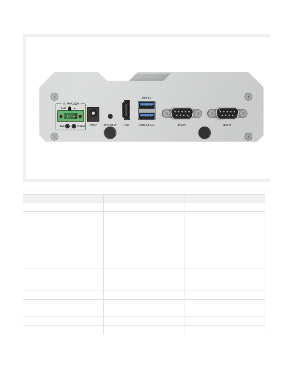
Figure Lite NX Back view
Interface Name Description
PWR1 Power interface 1 3Pin Terminal block52V DC IN
PWR2 Power interface 2 Round socket52V DC IN
PWR Led Carrier board status indicator White light: After power on, the power is
normal, First light the white light and the red
light flashes: the system start up is
unsuccessful, and then the system is
restarted. Red light is always on: the system
starts up 3 times without success, and the
system will not be restarted again. White
light is always on: the system starts up
normally. Yellow light: in the state of
shutdown, the power is switched on
STATUS Led System status indicator Light off: the system has not been started Re
d light: the system is starting Blue light: the
system is starting normally Yellow light: the
system is in refresh mode
RECOVERY Recovery Button Inter Recovery mode while pressing
HDMI HDMI HDMI 2.0 TYPE A 5V 1A
USB 2×USB 1×USB 3.0 1×USB 2.0Flashing Port 5V 1A
RS485_1 RS485 port 1 2.0VDC Min, 1mA Max
RS232_1 RS232 port 1 Logic1: -3V~-12VLogic0: 3V~12V1.6mA Max
RS485 Pin Assignment

Figure RS485 Pin Assignment
RS232 Pin Assignment
Port Name Pin Signal Description
RS485_1 1 NC NC
2 RS_485A RS485_1 A
3 RS_485B RS485_1 B
4 NC NC
5 GND GND
6-9 NC NC
Figure RS232 Pin Assignment
Port Name Pin Signal Description
RS232_1 1 NC NC
2 UART0_RXD RS232_1 recieve
3 UART0_TXD RS232_1 transmit
4 NC NC
5 GND GND
6-9 NC NC
UART Port Device Node
Relation of UART Port and device node as follow:
UART Port Name Device Node
RS232_1 ttyUART_232_1
RS485_1 ttyUART_485_1
Debug Port

The Debug Port(RS232) of Lite NX located on the PCBA, please refer to the folowing figure. PIN 8 RX, PIN 10 TX
Figure Debug Port
Figure Debug Port Signal
Expansion
Expansion device installation
Lite NX provides M.2 M Key, mini PCIe port for storage and communication expansion
Unscrew 8 screws and take off bottom cover of Lite NX while installation expansion device:

Figure Lite NX Screw Position1
Figure Lite NX Screw Position2
Este manual sirve para los siguientes modelos
2
Tabla de contenidos


