Microsemi PDS-EM-8100 Manual del operador

Microsemi 2.5G PoE Multiplexer
PDS-EM-8100
Quick Installation and
Initial Conguration
Schnelle Installation und
Erste Konguration
English
Deutsch

Copyright ©2016 Microsemi
CPG – PoE BU
Page 2
Notice
It is Microsemi’s policy to improve its products as new technology, components, software, and rmware
become available. Microsemi, therefore, reserves the right to change specications without prior notice.
Technical Support
If you encounter problems when installing or using this product, please consult the Microsemi website
at http://www.Microsemi.com.
USA/Canada: +1-949-380-6245

Copyright ©2016
PDS-EM-8100
Microsemi Page 3
English
Contents
CHAPTER 1 INTRODUCTION……………………………………………………………………….. 4
Overview……………………………………………………………………………………………………………4
MUX Front View…………………………………………………………………………………………………... 4
MUX Rear View…………………………………………………………………………………………………… 5
LED Descriptions…………………………………………………………………………………………………. 5
Reset Button……………………………………………………………………………………………………. 7
CHAPTER 2 INSTALLING THE MUX……………………………………………………………... 8
Package Contents…………………………………………………………………………………………………8
Mounting the MUX on a Wall……………………………………………………………………………………. 8
Connecting the AC Power Cord………………………………………………………………………………….9
CHAPTER 3 CONFIGURATION AND UPGRADE………………………………………….... 10
Conguring the Switch Dynamic Link Aggregation Function……………………………………………….... 10
Software upgrade………………………………………………………………………………………………… 12
CHAPTER 4 TROUBLESHOOTING……………………………………………………………..... 13
CHAPTER 5 SAFETY AND WARNING…………………………………………………………... 14
Important Safety Information……………………………………………………………………………………..14
AC Power Cord Set…………………………………………………………………………………………….. 14
Warnings!………………………………………………………………………………………………………...14
CHAPTER 6 SPECIFICATIONS……………………………………………………………………... 15
Functions and Features………………………………………………………………………………………….. 15
Standard compliance……………………………………………………………………………………………...15
Environmental Specications……………………………………………………………………………………. 15
Electrical Specications………………………………………………………………………………………….. 16
Ethernet Interface………………………………………………………………………………………………….16

Copyright ©2016 Microsemi
CPG – PoE BU
Page 4
Chapter 1 Introduction
Overview
This user guide describes the installation, conguration and troubleshoot of the Microsemi PDS-EM-8100,
a 3-Port 2.5G MUX. It provides instructions for the following tasks:
●Checking the MUX status based on the LED indications
●Resetting the MUX
●Installing the MUX
●Troubleshooting the MUX
MUX Front View
Figure 1: MUX Front Panel

Copyright ©2016
PDS-EM-8100
Microsemi Page 5
English
MUX Rear View
Figure 2: MUX Rear Panel
LED Descriptions
The LEDs on the front panel indicate the MUX status and allow monitoring. There are three types of
LEDs as follows:
●System LED - Indicates if the MUX is powered up correctly via the AC input.
●PoE LED - Indicates if the port is enabled and supplying power to powered devices (PD).
●Port Data Status LEDs - Indicate the current status of each port.
The following tables detail the functions of the LED indicators:
Table1: System LED
LED Color State Description
System Green
On The MUX is powered on correctly.
O The MUX is not receiving power.
Table 2: PoE LED
LED Color State Description
PoE Green
On The port is enabled and supplying power to
powered devices
Blink An abnormal state, such as overload, has been
detected in the MUX.

Copyright ©2016 Microsemi
CPG – PoE BU
Page 6
The table below details the port status according to the LED indications:
Table 3: Port Status LEDs
LED Color State Description
1GbRJ45 Ports
Green On
The port is enabled and established a link to a
connected device, and the connection speed is
1000Mbps.
Green Blinking The port is transmitting/receiving packets, and
the connection speed is 1000Mbps.
Amber On
The port is enabled and established a link to a
connected device, and the connection speed is
10/100Mbps.
Amber Blinking The port is transmitting/receiving packets, and
the connection speed is 10/100Mbps.
-- O
The port has no active network cable connected,
or it has not established a link to a connected
device. Otherwise, the port may have been
disabled through the MUX user interface.
2.5GbRJ45 Ports
Green On
The port is enabled and established a link to a
powered device, and the connection speed is
2.5Gbps.
Green Blinking The port is transmitting/receiving packets, and
the connection speed is 2.5Gbps.
Amber On
The port is enabled and established a link to a
powered device, and the connection speed is
100/1000Mbps.
Amber Blinking The port is transmitting/receiving packets, and
the connection speed is 100/1000Mbps.
-- O
The port has no active network cable connected,
or it has not established a link to a connected
device. Otherwise, the port may have been
disabled through the MUX user interface.

Copyright ©2016
PDS-EM-8100
Microsemi Page 7
English
Reset Button
Pressing the Reset Button for 5 seconds resets the MUX. This will reboot the MUX and reset it back to
the last saved conguration settings.
_____________________________________________________________________________________
Note:
The table below shows the LED indications while pressing the Reset button. Once the LED indications
detailed below are correctly displayed, the Reset button can be released.
_____________________________________________________________________________________
Table 4: Reset Button LED indications
Task Performed SYS LED
Indication
Port Status LED
Indication
Reset the MUX Blinking
Green ALL LEDs Light OFF
Copyright ©2016 Microsemi
CPG – PoE BU
Page 8
Chapter 2 Installing the MUX
Package Contents
●The MUX
●AC power cord
_____________________________________________________________________________________
Note:
The MUX is an indoor device. If it is to be used with outdoor devices such as outdoor IP cameras or
outdoor WiFi APs, then you are strongly advised to install a surge protector or surge suppressor in
order to protect the MUX.
_____________________________________________________________________________________
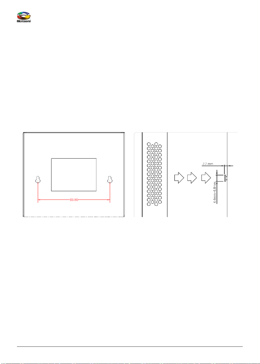
Mounting the MUX on a Wall
Step1: Install the user-supplied screws on the appropriate location on the wall as illustrated below,
paying attention to the distance between the screws and their size.
Figure 3: Installing screws on the wall

Copyright ©2016
PDS-EM-8100
Microsemi Page 9
English
Step2: Make sure that the MUX is securely attached to wall.
Figure 4: Attaching the MUX to the wall
Connecting the AC Power Cord
Step 1: Connect the AC power cord to the MUX’s AC power socket .
Step 2: Connect the other end of the AC power cord to the AC power outlet.
Step 3: Check the SYS LED. If it is ON, the power is correctly connected.
Figure 5: Connecting the AC Power Cord

Copyright ©2016 Microsemi
CPG – PoE BU
Page 10
Chapter 3 Conguration and Upgrade
Conguring the Switch Dynamic Link Aggregation Function
The link partner GbE switch on this 2.5Gb MUX has to be pre-configured, in order to enable two GbE
ports dynamic link aggregation on this switch. To connect these two ports from the switch to the MUX,
please refer to Figure 6 - 2.5Gb MUX Application Diagram below.
Figure 6: 2.5Gb MUX Application diagram
Port aggregation applies to various methods of combining (aggregating) multiple network connections
in parallel in order to increase throughput beyond what a single connection could sustain, and to
provide redundancy in case one of the links should fail.
Tabla de contenidos
Idiomas:
Manuales populares de Multiplexor de otras marcas


ADTRAN
ADTRAN Frameport 768 Manual de usuario

Elo TouchSystems
Elo TouchSystems E247 Manual de usuario

Paradyne
Paradyne Hotwire 8786 Manual de usuario

RFL Electronics
RFL Electronics 9508D UCC Manual de usuario

Miranda
Miranda AMX-101i Manual de instrucciones

ShipModul
ShipModul MiniPlex-AIX NMEA-0183 Manual de usuario


