
MICRO-AIR DDT4830 Manual de usuario

MICRO-AIR DOWNDRAFT TABLES
INSTALLATION AND OPERATION MANUAL
DDT4830 & DDT7230
Includes Installation, Operation, and Service Instructions
IMPORTANT
This manual contains specic cautionary statements relative to worker safety. Read this manual thoroughly and follow
as directed. It is impossible to list all of the hazards of dust control equipment. It is important that use of the equipment
be discussed with a Micro-Air® Representative. Persons involved with the equipment or systems should be instructed
to operate in a safe manner.

MICRO AIR® DDT
CLEAN AIR SYSTEMS
2
DDT MICRO AIR®
CLEAN AIR SYSTEMS
3
!
CAUTION
• Avoid mixing combustible materials, such as bufng
lint, paper, wood, aluminum, and magnesium dust,
and with dust generated from grinding ferrous metals
due to the potential re hazard caused by sparks in
the dust collector.
• Under no conditions should the persons operating
the dust collector be allowed to put cigarettes or any
burning object into the hood or ducting of any dust
collector system.
• All users of Micro-Air® Equipment should comply
with all National and Local Fire Codes and / or other
appropriate codes when determining the location and
operation of dust control equipment.
SPECIFICATIONS
CABINET DIMENSIONS AND WEIGHTS
4830 57 3/4” max. H x 48 3/8” W x 30” D 255lbs.
7230 57 3/4” max. H x 72 3/8” W x 30” D 285lbs.
DUST TRAY CAPACITY (OPTIONAL)
432 Cubic inches total
INSTALLATION
INSPECTION
The Micro-Air® Clean Downdraft Table is shipped on
multiple skids. All skids should be inspected for any
visible damage that may have occurred during shipment.
Additional equipment that maybe shipped separately
includes:
Drop-Out Kits Dust-Tray Kits
Hopper Collars Wheel Kit
Grills
EQUIPMENT / TOOLS REQUIRED
Equipment and tools needed for proper installation will
include the following:
Crane or Lift Truck 1/2” Concrete Drill Bit
Wrench 1/2” Anchors
Drill
ASSEMBLY OF UNIT
1. Remove packaging from table and legs.
NOTE: Leg assembly can be completed while unit is
upside down on skid.
2. Place leg on the inside of leg bracket. Align holes in
leg to corresponding holes in leg bracket (See FIG. 1).
The leg can be installed in three different positions.
The shortest position will give an approximate table
height of 30”, the middle setting 33” and the tallest
setting 36”.
3. Attach leg with provided hardware. Insert all 4 bolts
before tightening the nuts.
FIG. 1
4. Install optional components prior to turning the unit
over. See installation procedure for optional
components on pages 3 through 7.
5. Determine location for downdraft table. The table
must be located on a hard at surface capable of
holding 1/2” anchor bolts.
6. Move table to location and mark location for anchor
bolts. (Unless wheel kit is installed)
7. Move table out of area, drill appropriate holes and
place 1/2” anchor bolts.
8. Move/lift table back into position over anchors.
9. Secure table with appropriate nuts/washers.
10. Place appropriate grills on the table.
11. Proceed with installation of optional components.
12. Connect ductwork to collars on the bottom of the
hoppers.
Recommended air ow:
Operation Face Velocity CFM 48” Table CFM 72” Table
Heavy Grinding 250-300 FPM 2500 CFM 3750 CFM
Welding 200-250 FPM 2000 CFM 3000 CFM
Fine Dusts 175-200 FPM 1750 CFM 2625 CFM
USE 5/16” HARDWARE
(PROVIDED)

MICRO AIR® DDT
CLEAN AIR SYSTEMS
2
DDT MICRO AIR®
CLEAN AIR SYSTEMS
3
DDT SHIELD INSTALLATION PROCEDURE
This Kit Includes:
ITEM PART NO. DESCRIPTION QTY ADDITIONAL INFORMATION
1 37825-01 Shield Assembly 1 DDT4830 Only
37825-02 Shield Assembly 1 DDT7230 Only
2 P3543 Self Tapping Screw 3 DDT4830 Only
P3543 Self Drilling/Self Tapping Screw 5 DDT7230 Only
INSTALLATION
1. Remove Shield Assembly from packaging. Inspect for any possible damage incurred during shipment.
NOTE: Grills must be installed prior to installing Shield Assembly.
2. Set Shield Assembly on top of the assembled Downdraft Table. The Screw Plates should overlap at the rear of the
table.
3. Center Shield Assembly on table. Verify side shields can move freely.
4. Attach Shield Assembly with provided Self Drilling/Self Tapping Screws.
1
2
FIG. 2

MICRO AIR® DDT
CLEAN AIR SYSTEMS
4
DDT MICRO AIR®
CLEAN AIR SYSTEMS
5
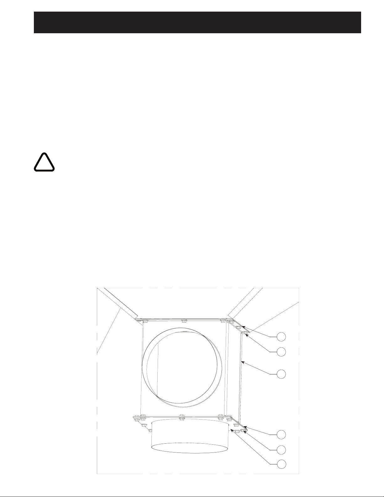
DDT COLLAR KIT INSTALLATION PROCEDURE
This Kit Includes:
ITEM PART NO. DESCRIPTION QTY
1 37815-01 Hopper Collar 2
2 P3543 Self Drilling/Self Tapping Screw 24
3 P1031 1/4” x 1/2” Foam 80 Inches
INSTALLATION
1. Remove Collar Kit from packaging. Inspect for any possible damage incurred during shipment. If this is a new
table, assembly can be done while table is upside down.
!
CAUTION
Some assembly steps may require lifting and should only be done using proper lifting techniques.
2. Remove backing and place foam on Collar Plate. Foam should cover holes.
3. Line up hole pattern on Collar Plate with hole pattern on Hopper.
4. Screw in twelve screws.
5. Repeat for second hopper.
3
2
1
FIG. 3
MICRO AIR® DDT
CLEAN AIR SYSTEMS
4
DDT MICRO AIR®
CLEAN AIR SYSTEMS
5
5
DDT HOPPER DROP-OUT KIT INSTALLATION PROCEDURE
This Kit Includes:
ITEM PART NO. DESCRIPTION QTY.
1 37835-01 Hopper Drop-Out (1 Collar) 2
37835-02 Hopper Drop Out (2 Collars) Optional
2 P3543 Self Drilling/Tapping Screws 24
3 37848-01 Drop Out Blank Plate 2
37815-01 Collar Optional
INSTALLATION
1. Remove Hopper Drop-Out kit from packaging. Inspect for any possible damage incurred during shipment. If this is
a new table assembly can be done while table is upside-down.
!
CAUTION
Some assembly steps may require lifting and should only be done using proper lifting techniques.
2. Remove backing and place foam on Drop-Out anges.
3. Line up hole pattern on Hopper Drop-Out anges with hole pattern on Hopper. The Drop-Out Assembly
can be rotated to accommodate duct location.
4. Screw in twelve screws.
NOTE: Drop-Out Blank Plate can be modied to allow for custom Drop-Out containers.
5. Remove backing and place foam on the Blank Drop-Out Plate.
6. Line up hole pattern on Drop-Out Blank Plate with hole pattern on anges of Hopper Drop-Out.
7. Attach Drop-Out Blank Plate using provided 1/4” hardware.
8. Hopper Collar can be substituted for the Drop-Out Blank Plate (As Shown in FIG. 4).
9. Repeat for second hopper.
ITEM PART NO. DESCRIPTION QTY.
4 P164 1/4-20 Hex Bolt 12
P1729 1/4 Washer 24
P203 1/4-20 Nut 12
P242 1/4 Lock Washer 24
5 P1031 1/4 x 1/2 Foam 160 Inches
2
1
5
4
3
FIG. 4

MICRO AIR® DDT
CLEAN AIR SYSTEMS
6
DDT MICRO AIR®
CLEAN AIR SYSTEMS
7
DDT DUST TRAY KIT INSTALLATION PROCEDURE
This Kit (37840-01) Includes:
ITEM PART NO. DESCRIPTION QTY.
1 37841-01 Dust Tray Wrap 2
2 37842-01 Drawer 2
3 P3506 Knob 2
4 P3686 Foam 60 Inches
5 P164 1/4-20 Hex Bolt 12
P1729 1/4 Washer 24
P203 1/4-20 Nut 12
P242 1/4 Lock Washer 24
INSTALLATION
1. Remove Dust Tray Kit from packaging. Inspect for any possible damage incurred during shipment. If this is a new
table assembly can be done while table is upside-down.
!
CAUTION
Some assembly steps may require lifting and should only be done using proper lifting techniques.
2. Remove backing and place foam on Dust Tray Wrap anges.
3. Line up hole pattern on Dust Tray Wrap anges with hole pattern on Drop-Out. The Dust Tray Wrap can be
rotated to accommodate drawer removal.
4. Attach Dust Tray Wrap using provided 1/4” hardware.
5. Slide Drawer into Dust Tray Wrap and secure using provided Knobs.
6. Repeat for second hopper.
3
2
5
4
1
FIG. 5

MICRO AIR® DDT
CLEAN AIR SYSTEMS
6
DDT MICRO AIR®
CLEAN AIR SYSTEMS
7
DDT WHEEL KIT INSTALLATION PROCEDURE
This Kit Includes:
ITEM PART NO. DESCRIPTION QTY. ADDITIONAL INFORMATION
1 P2334 Swivel Caster Wheel 4
2 37820-03 30” Leg Brace 2
3 37820-01 48” Leg Brace 2 (DDT4830 Only)
37820-03 72” Leg Brace 2 (DDT7230 Only)
4 P164 1/4-20 Hex Bolt 16
P1729 1/4 Washer 32
P203 1/4-20 Hex Nut 16
P242 1/4 Lock Washer 32
5 P146 1/2-13 Hex Nut 4
P147 1/2 Lock Washer 4
P3314 1/2 Flat Washer 4
INSTALLATION
1. Remove wheel kit from packaging. Inspect for any possible damage incurred during shipment. If this is a new
table assembly can be done while table is upside-down.
!
CAUTION
Some Assembly steps require lifting and should only be done using proper lifting techniques.
2. Lift the short end of the table approximately 6” above the oor.
3. Insert threaded shaft of caster through the hole in the bottom of the leg.
4. Repeat for second leg.
5. Place washers and nut on the threaded shaft, Tighten.
6. Lower the end and block so it cannot move.
7. Repeat steps 2 through 6 for the opposite end.
8. Using the provided 1/4” hardware attach the leg braces (See Figure 6). The braces may be lowered or raised to
accommodate ductwork.
9. Remove blocks used to hold table.
2
4
1
3
5
FIG. 6

MICRO AIR® DDT
CLEAN AIR SYSTEMS
8
DDT MICRO AIR®
CLEAN AIR SYSTEMS
9
ITEM PART NO. DESCRIPTION
1. 37800-01 48” x 30” Downdraft Table
37800-02 72” x 30” Downdraft Table
2. 37825-01 48” Back/Side Shield
37825-02 72” Back/Side Shield
3. P2334 Swivel Caster Wheels
4. 37820-01 30” Leg Brace
5. 37820-02 48” Leg Brace
37820-03 72” Leg Brace
6. 37815-01 Hopper Collar
ITEM PART NO. DESCRIPTION
37840-01 Drawer/Wrap Assembly (Drawer, Knob,
& Wrap)
7. 37842-01 Dust Tray Drawer
8. P3506 Knob
9. 37841-01 Dust Tray Wrap
10. 37835-01 Hopper Drop-Out One Collar
37835-02 Hopper Drop-Out Two Collars
11. 37807-01 Black Painted Grill
37808-01 Rubberized Grill
P2330 Aluminum Grill
P2331 Fiberglass Grill
11
4
6
2
1
3
5
7
8
9
10
FIG. 7
DDT PARTS LIST

MICRO AIR® DDT
CLEAN AIR SYSTEMS
8
DDT MICRO AIR®
CLEAN AIR SYSTEMS
9
NOTES

P.O. BOX 1138 • WICHITA, KS. 67201
(316) 943-2351 • FAX (316) 943-2717
INFO@MTLFAB.COM
©METAL-FAB, INC. Form No. L2002 9-02
6981
Litho in U.S.A.
MICRO AIR® DDT
CLEAN AIR SYSTEMS
NOTES
Este manual sirve para los siguientes modelos
1
Tabla de contenidos


