Metrohm 750 Autosampler Manual de usuario

CH-9101 Herisau/Switzerland
Tel. ++41 71 353 85 85
Fax ++41 71 353 89 01
Internet www.metrohm.ch
E-Mail [email protected]
750 Autosampler
2.750.0020 Instrument version
8.750.1023 Instructions for Use
23.02.2000 / dö

Table of contents
750 Autosampler I
Table of contents
1Introduction............................................................................................1
1.1 Instrument description.............................................................................1
1.2 Theory of operation ..................................................................................2
1.3 Control elements.......................................................................................4
1.4 Information on the Instructions for Use................................................6
1.4.1 Organization....................................................................................6
1.4.2 Notation and pictograms ................................................................7
1.5 Safety notes ...............................................................................................8
1.5.1 Electrical safety ...............................................................................8
1.5.2 General precautionary rules............................................................8
2Installation..............................................................................................9
2.1 Setting up the instrument........................................................................9
2.1.1 Packaging .......................................................................................9
2.1.2 Check..............................................................................................9
2.1.3 Location...........................................................................................9
2.2 Connection to IC system........................................................................10
2.2.1 750 Autosampler as "Master"........................................................ 10
2.2.2 732 IC Detector as "Master" ..........................................................11
2.2.3 Connection to 762 with «IC Net»...................................................12
2.2.4 Tubing connection ........................................................................14
2.3 Mains connection....................................................................................15
2.3.1 Check fuses ..................................................................................15
2.3.2 Mains cable and mains connection..............................................16
2.3.3 Switching the instrument on/off ....................................................16
2.4 Initial checkout ........................................................................................17
3Operation...............................................................................................19
3.1 Fundamentals of operation ...................................................................19
3.1.1 Display and instrument dialog ......................................................19
3.1.2 Overview of key functions .............................................................20
3.2 System settings.......................................................................................23
3.3 Manual rinsing.........................................................................................26
3.4 Manual injection......................................................................................26
3.5 Methods ....................................................................................................28
3.6 Method procedure...................................................................................34
3.7 Priority sample.........................................................................................35
3.8 Remote control........................................................................................36

Inhaltsverzeichnis
750 Autosampler
II
4Notes – Maintenance – Faults...................................... 39
4.1 Operating information............................................................................ 39
4.1.1 Loading sample vials.................................................................... 39
4.1.2 Sample preparation ...................................................................... 39
4.1.3 Operating parameters................................................................... 40
4.2 Maintenance and servicing ................................................................... 41
4.2.1 General information ...................................................................... 41
4.2.2 Transfer needle replacement........................................................ 41
4.2.3 Sample preparation ...................................................................... 42
4.3 Remedying malfunctions....................................................................... 43
4.3.1 Non-reproducible injections ......................................................... 43
4.3.2 Missed injections.......................................................................... 44
4.4 Error messages....................................................................................... 45
4.4.1 Entry error messages.................................................................... 45
4.4.2 System error messages................................................................ 47
4.4.3 Remote control error codes.......................................................... 48
5Appendix ................................................................................................ 49
5.1 Technical data ......................................................................................... 49
5.2 Interfaces.................................................................................................. 51
5.2.1 Contact closure strips................................................................... 51
5.2.2 RS232 interface............................................................................. 53
5.3 Standard equipment............................................................................... 54
5.4 Optional accessories.............................................................................. 55
5.5 Warranty and conformity....................................................................... 56
5.5.1 Warranty........................................................................................ 56
5.5.2 EU Declaration of conformity........................................................ 57
5.5.3 Certificate of conformity and system validation............................ 58
5.6 Index.......................................................................................................... 59
List of figures
Fig. 1:Autosampler 750 ............................................................................................... 1
Fig. 2:Positive displacement sample injection ............................................................ 2
Fig. 3:Displacement volume versus needle position .................................................. 3
Fig. 4:Front of 750 Autosampler.................................................................................. 4
Fig. 5:Rear of 750 Autosampler................................................................................... 5
Fig. 6:Connection of 750 Autosampler to 732/733 ................................................... 11
Fig. 7:Connection of 750 Autosampler to 732/733 and 762 ..................................... 13
Fig. 8:Keypad ............................................................................................................ 20
Abb. 9:Manual sample filtering ................................................................................... 39
Fig. 10:Sample filtering with FilterCaps....................................................................... 40
Fig. 11:Transfer needle replacement........................................................................... 51
Fig. 12:Valve control .................................................................................................... 57
Fig. 13:Inputs/outputs.................................................................................................. 51

1.1 Instrument description
750 Autosampler 1
1 Introduction
1.1 Instrument description
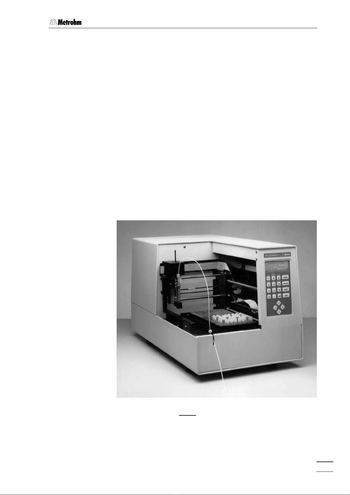
The 750 Autosampler is a microcomputer-operated sampling/con-
troller system designed to be used with the ion chromatographic in-
struments 732 IC Detector and 733 IC Separation Center. It has a ca-
pacity of up to 128 samples, which are transferred automatically into
the sample loop of the 733 IC Separation Center.
The 750 Autosampler performs up to four, fixed loop injections per vial
at user-selectable time intervals. All operating parameters are entered
from the front panel. Additionally, the instrument can be controlled re-
motely either by an externally programmable contact closure or through
the RS232 connector located on the rear panel.
Fig. 1: 750 Autosampler

1 Introduction
750 Autosampler
2
1.2 Theory of operation
Displacement principle
The 750 Autosampler operates using the positive displacement princi-
ple of sample transfer. This sample transfer process into the sample
loop of the 733 IC Separation Center is illustrated in Fig. 2. When an in-
jection is initiated, the hollow transfer needle 55 descends into the vial.
The needle tip punctures the polyethylene cap of the sample vial. The
opening into the needle is located on the side to minimize plugging by
cap material as the cap is punctured. The needle continues downward
until the pushrod contacts the area around the puncture in the cap
which forces the cap down into the vial. The piston action of the cap
pressurizes the sample and forces it up through the needle and the
transfer tubing 88 that is connected to the needle. From the transfer
tubing, the sample flows through the injection valve and sample loop
with the excess passing on through the waste tube to a waste con-
tainer.
Rinsing by air bubbles
The air bubble (minimum 150 µL), which is always present at the top of
a properly filled and capped vial, precedes the sample stream through
the plumbing. The bubble disrupts the laminar flow of the fluid in the
tubing while pushing out the previous sample and solvent. This effect,
in addition to the large excess volume of sample, helps to minimize
sample carryover.
RUN FILL/LOAD INJECT RUN
A B C D
Fig. 2: Positive displacement sample injection
Column
Waste
Eluent
Sample
Needle
Cap
Sample vial
Valve

1.2 Theory of operation
750 Autosampler 3
Number of injections
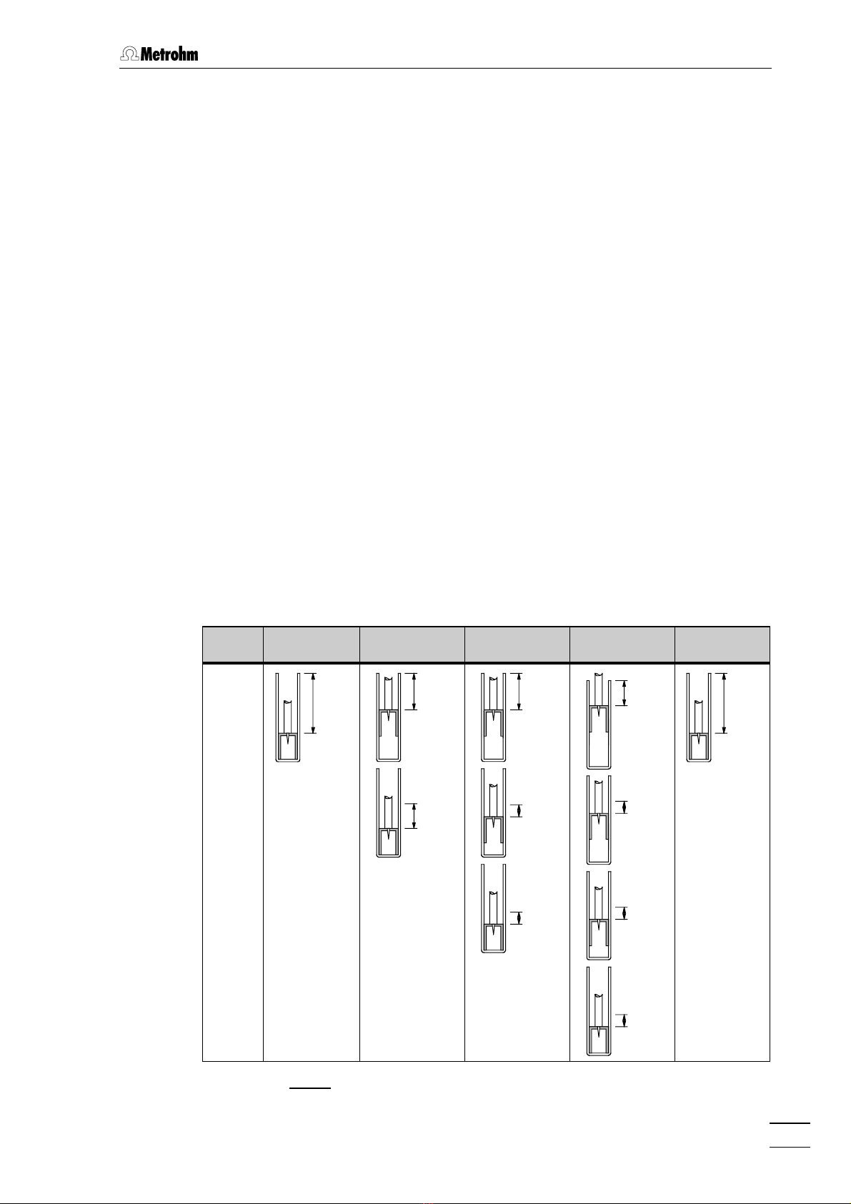
The number of injections per sample with the 750 Autosampler de-
pends on the sample loop size. With sample loops >10 µL max. 3,
with sample loops ≤10 µL max. 4 injections are possible. Fig. 3 details
the needle position and displacement volume at the sample delivery
action. Care should always be taken that the injection volume is at least
three times greater than the volume of the sample loop. This is why only
a maximum of 2 injections per sample should be made with 100 µL
loops; the minimum sample volume is 300 µL for 1 and 600 µL for 2 in-
jections. For sample loops with a volume ≤10 µL up to 4 injections per
sample are possible. The minimum sample volume required is 150 µL
for 1, 300 µL for 2, 450 µL for 3 and 600 µL for 4 injections.
Rinsing
Rinsing will be necessary for highly concentrated samples or for sam-
ples that may absorb in the tubing or in the injection valve. Rinse vials
are filled with eluent or other suitable solvent. The Rinse process is
shown in Fig. 3. Rinse vials can be used either after each vial (every
even numbered or odd numbered vial) or at programmed vial intervals.
There are two types of Rinses, the Normal Rinse and the Quick Rinse.
The Normal Rinse occurs after all the injections have been made from
the sample vial and the run time has elapsed. A Quick Rinse occurs
immediately after an injection and is used in applications where the
sample solution must not be left in the needle, transfer tubing or valve
for whatever reason. Only one injection per vial can be programmed
when using a Quick Rinse.
Injection 1 Injection
per vial 2 Injections
per vial 3 Injections
per vial 4 Injections
per vial Rinse
1
2
3
4
2.65 cm
730 µL
1.63 cm
450 µL
1.02 cm
280 µL
1.63 cm
450 µL
0.51 cm
140 µL
0.51 cm
140 µL
1.12 cm
310 µL
0.51 cm
140 µL
0.51 cm
140 µL
0.51 cm
140 µL
2.65 cm
730 µL
Fig. 3: Displacement volume versus needle position

1 Introduction
750 Autosampler
4
1.3 Control elements
750 Autosampler
RINSEINJECTION
MANUAL
METHOD
REM/LOCTEMPSYSTEM
F3F2F1
4
7
.CLEAR
1
0
8 9
5 6
2 3
FUNCTION
RUN/STOP
PRIORITY
ENTER
11
22
33
44
556677
88
Fig. 4: Front of the 750 Autosampler
11 Display (LCD)
comprising 4 lines each of
20 characters
55 Transfer needle
22 Keypad
with function, numeric and cursor
keys (details see chap. 3.1.2)
66 Holder for transfer tubing
33 Sample rack (6.2041.600)
for 128 sample vials
77 Holder stopper
44 Sample vial
6.2743.000 sample vial (PP) or
6.2413.000 sample vial (glass)
88 Transfer tubing
6.1803.000 PTFE capillary for the
connection of the 750 Autosampler
with the injector of the 733 IC
Separation Center

1.3 Control elements
750 Autosampler 5
Hz
VA
V
Type:
U:
f:
Nr.:
S:
Switzerland
99
1010
1212
1313
1414
1515
RS-232
PRINTER
EXT PWR
CONTROL
BCD
IEEE
INJECT
LOAD
1111
Fig. 5: Rear of the 750 Autosampler
99 Contact closure strip for valve
control
details see chap. 5.2.1
1313 Mains switch
switch to switch the instrument on
and off: I = ON 0 =
OFF
1010 Contact closure strip for external
control
details see chap. 5.2.1
1414 Mains connection plug
mains connection see chap. 2.3
1111 RS232 interface
details see chap. 5.2.2 1515 Fuse cassette
changing the fuses, see chap. 2.3.1
1212 Model plate
with instrument and serial number,
mains voltage, mains frequency,
power consumption

1 Introduction
750 Autosampler
6
1.4 Information on the Instructions for Use
Please read through these Instructions for Use carefully before you put
the 750 Autosampler into operation. The Instructions for Use contain
information and warnings which must be heeded by the user to assure
safe operation of the instrument.
1.4.1 Organization
These 8.750.1023 Instructions for Use for the 750 Autosampler pro-
vide a comprehensive overview of the installation, startup procedure,
operation, fault rectification and technical specifications of the instru-
ment. The Instructions for Use are organized as follows:
Section 1 Introduction
General description of instruments, control parts
and safety notes
Section 2 Installation
Installation of the 750 Autosampler, connection to
IC Separation Center 733, initial checkout
Section 3 Operation
Detailed description of the operation and
explanation of functions of all keys
Section 4 Notes – Maintenance – Faults
Notes on operation, maintenance,
fault rectification, diagnostic tests
Section 5 Appendix
Technical data, interfaces, standard equipment,
options, warranty, declarations of conformity, index
To find the required information on the instruments, you will find it an
advantage to use either the Table of contents or the Index at the
back.

1.4 Information on the Instructions for Use
750 Autosampler 7
1.4.2 Notation and pictograms
The following notations and pictograms (symbols) are used in these In-
structions for Use:
<PARAM> Key
"Run Time"Parameter or entry value
55 Control element of 750
(see chap. 1.3)
8484 Control element of 732/733
(see Instructions for Use 732)
1414 Control element of 762
(see Instructions for Use 762)
READY
SELECT A FUNCTION
Display
Text in display 11 of the 750 Auto-
sampler
Hazard
This symbol draws attention to a
possible danger to life or of injury if
the associated directions are not
followed correctly.
Warning
This symbol draws attention to
possible damage to instruments or
instrument parts if the associated
directions are not followed cor-
rectly.
Caution
This symbol marks important in-
formation. First read the associ-
ated directions before you con-
tinue.
Comment
This symbol marks additional in-
formation and tips.
Tabla de contenidos
Manuales populares de Dechado de otras marcas

Akai
Akai MPCX Manual de usuario

KAM
KAM Simple Precision IAS Manual de usuario

YZ Systems
YZ Systems DynaPak DP-2010FU Manual de lista de piezas

YZ Systems
YZ Systems DynaPak 2010N Series Manual de usuario

YZ Systems
YZ Systems DynaPak DP-2010UX Manual de lista de piezas

Novation
Novation Circuit Rhythm Manual de usuario