Metro DataVac M3 Manual de usuario

+33 (0) 450 39 08 49
Metro Fax +33 (0) 450 39 08 33
80 impasse des chapotines web www.metro-fr.com
ZAE Chez Merlin
F-74420 St-André de Boëge
France E-mail info@metro-fr.com
M
M3
3
F
Fo
or
r
i
in
nd
du
uc
ct
ti
iv
ve
e,
,
1
1V
Vp
pp
p
a
an
nd
d
T
TT
TL
L
p
pr
ro
ob
be
es
s
USER’S MANUAL
Firmware 3.0

M3
Page 2
1. TABLE OF CONTENTS
1.TABLE OF CONTENTS ___________________________________________ 2
2.FOREWORDS __________________________________________________ 4
3.INTRODUCTION ________________________________________________ 5
3.1.PRODUCT PRESENTATION ........................................................................ 5
3.2.VERSIONS .................................................................................................... 5
3.3.CHARACTERISTICS ..................................................................................... 6
3.3.1.MAIN TECHNICAL CHARACTERISTICS ............................................... 6
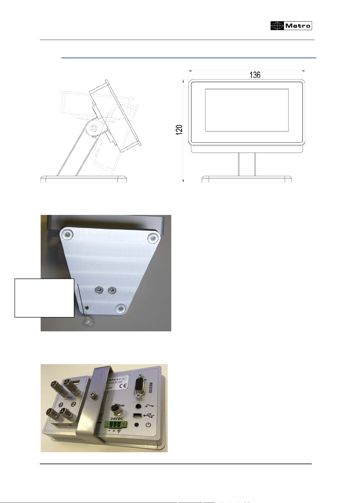
3.3.2.DIMENSION AND INSTALLATION ........................................................ 7
3.3.3.CONTENTS OF THE PACKAGING ........................................................ 8
3.3.4.OPTIONS ................................................................................................ 8
3.3.5.CONNECTORS .................................................................................... 13
3.3.5.1.VERSION FOR INDUCTIVE PROBES .............................................. 13
3.3.5.2.VERSION FOR INCREMENTAL PROBES AND ENCODERS .......... 14
3.3.6.RS232 COMMUNICATION PORT ........................................................ 15
3.3.7.MINI-USB CONNECTOR ...................................................................... 15
3.3.8.THE 24VDC CONNECTOR .................................................................. 16
3.3.9.THE USB STICK CONNECTOR ........................................................... 16
3.3.10.THE FOOTSWITCH CONNECTOR ................................................... 16
4.GRAPHICAL INTERFACE ________________________________________ 17
4.1.2 MAIN PARTS ............................................................................................ 17
4.2.GENERALITIES ........................................................................................... 19
4.3.CONFIGURATION WINDOWS .................................................................... 21
4.4.VIRTUAL KEYBOARD ................................................................................. 22
5.CONFIGURATION OF THE DEVICE AND THE MEASURE ______________ 23
5.1.DEFINITION ................................................................................................. 24
5.1.1.PART 1 ................................................................................................. 25
5.1.2.PART 2 ................................................................................................. 29
5.1.3.PART 3, CLASS ................................................................................... 30
5.1.4.PART 4, CONTROL LIMIT .................................................................... 32
5.2.DISPLAY ...................................................................................................... 33
5.3.SETUP ......................................................................................................... 35
5.3.1.GENERALITIES .................................................................................... 36
5.3.2.INDUCTIVE PROBE ............................................................................. 37
5.3.3.HEIDENHAIN PROBE (11µA OR VCC) ............................................... 37
5.3.4.TTL PROBE WITH HEINDEHAIN PINOUT .......................................... 38
5.3.5.M-BUS MODULES ............................................................................... 39
5.3.6.AIR GAGE MB-AG MODULE ............................................................... 44
5.4.CONFIGURATION ....................................................................................... 49
5.5.LOCKING ..................................................................................................... 52
5.6.MEASURE ................................................................................................... 54
6.MEASURING SCREEN __________________________________________ 55
6.1.LATERAL BUTTON FUNCTIONS ............................................................... 55
6.2.CHOICE OF THE NEEDLE INDICATOR STYLE ......................................... 58
6.3.TEMPORARY DYNAMIC MODE ................................................................. 59
6.4.DISPLAY MODE WITHOUT TOLERANCE .................................................. 60
7.USB COMMUNICATION _________________________________________ 61

M3
Page 3
8.RS232 COMMUNICATION _______________________________________ 63
8.1.COMMANDS ................................................................................................ 63
8.1.1.GENERALITIES .................................................................................... 63
8.1.2.COMMAND LIST .................................................................................. 64
8.1.2.1.WINDOW PART ................................................................................ 64
8.1.2.2.WINDOW DISPLAY ........................................................................... 65
8.1.2.3.WINDOW CONFIGURATION ............................................................ 65
8.1.2.4.WINDOW « LOCK » .......................................................................... 66
8.1.2.5.MEASURING SCREEN ..................................................................... 66
9.DATA EXPORT ON USB KEYS ____________________________________ 67
9.1.STANDARD MODE : ................................................................................... 67
9.2.ADVANCED MODE : ................................................................................... 68
10.CONFIGURATION OF THE UNIT WITH QR CODES ___________________ 69
11.RTU MODBUS protocol __________________________________________ 70
12.OPTIONAL M-BUS MODULES ____________________________________ 73
12.1.MB-IO MODULE (SEE ALSO CHAP 5.3.5) .............................................. 73
12.2.MB-RL MODULE ....................................................................................... 76
12.3.MB-TP MODULE – FOR TEMPERATURE COMPENSATION .................. 79
13.FACTORY RESET ______________________________________________ 84
14.FIRMWARE UPDATE ___________________________________________ 85
15.EXEMPLES OF PROBE COMBINATIONS ___________________________ 87
15.1.SIMPLE MEASUREMENTS WITH ONE PROBE ...................................... 87
15.2.COMBINED MEASUREMENTS WITH TWO PROBES ............................. 87

M3
Page 4
2. FOREWORDS
ONE YEAR LIMITED GUARANTEE
MANUFACTURER'S RESPONSIBILITY
SPARE PARTS AND LABOUR.
The manufacturer commits himself to pay for repair or replacement costs (labour
costs included) during a period of one year as from the date the guarantee came into
force. The spare parts can be new or renovated and are guaranteed until the end of
the initial guarantee period.
FIRST END-USER COVERAGE.
This guarantee applies only to the first end-user of the product and is not assignable
to any other subsequent purchaser or user.
RESTRICTIONS.
Any accessory or expansion item not included in the original factory packaging is not
guaranteed.
The present guarantee does not cover: installation or repair costs, damages resulting
from circumstances beyond the manufacturer's control like damages following acts of
God, misuse, or careless mistake from the user, damages during the transport or due
to a wrong installation, use or application, such as any material damage caused by
the use of non supplied products, components or accessories. It also does not cover
products modified without any written approval from the manufacturer, including
electrical or mechanical modification, removal of serial numbers or of the
manufacturer's trademarks or of any other identification.
THE SOLE RECOURSE UNDER THIS GUARANTEE SHALL BE THE REPAIR OR
THE REPLACEMENT OF DEFECTIVE PARTS AS INDICATED ABOVE. UNDER
NO CIRCUMSTANCES THE MANUFACTURER CAN BE HELD LIABLE FOR
INDIRECT OR SPECIAL DAMAGES OR FOR DAMAGES RESULTING FROM THE
USE OF THE PRODUCT, INCLUDING ANY LOSS OF DATA, BUSINESS OR
PROFIT, AND WHETHER THESE DAMAGES CAN BE FORESEEN OR NOT AND
WHETER THEY ARE BASED ON A GUARANTEE VIOLATION OR NOT.
THE PRESENT GUARANTEE REPLACES ANY OTHER EXPRESSED OR IMPLIED
GUARANTEE INCLUDING BUT NOT LIMITED TO ANY GUARANTEE OF
MARKETING OR ADEQUACY FOR A PARTICULAR USE; AND ALL THESE
GUARANTEES ARE EXPRESSLY EXCLUDED AND CANCELLED.
WARNING
The information contained in this booklet can be changed without notice.
The manufacturer makes no warranty whatsoever with respect to the warranties of
commercial quality of this product or its suitability to a particular use.

M3
Page 5
The manufacturer is not responsible for mistakes that could be found in this handbook
and also for direct or indirect damage resulting from the equipment, its performances
and the use of this product.
It is the responsibility of the user to verify the calibration of the display before
measuring and it is advised to check periodically the calibration and
measurement performance.
CLEANING
Use a soft cotton cloth slightly soaked with an ethyl alcohol based product.
DO NOT USE the following products: acetone, benzene, toluene and halogens
hydrocarbons.
3. INTRODUCTION
3.1. PRODUCT PRESENTATION
The M3 display unit allows making dimensional control using 1 or 2 probes.
It is possible to make simple measurement (with one probe), or combined
measurement (with 2 probes): sums or differences. It is possible to display 1 or 2
characteristics on the screen and can make static measurement or dynamic (Max,
Min, Max-Min…)
The M3 can be connected to a PC thanks to its RS232 or USB connection.
A footswitch can be connected in order to transfer measurements.
3.2. VERSIONS
The following probes can be connected
M3 Reference Description
13000 2 x TTL probe or encoder : Direct
connection of Heidenhain and through
and adaptor for Magnescale (DK series)
and Mituto
y
o
(
LG series
)
13010 2 x inductive probes from Metro
13020 2 x incremental probes or encoder from

M3
Page 6
Heidenhain with a 11µA or 1Vpp output
1301T 2 inductive probe with a Tesa
compatibilit
y
1301M 2 x inductive probe from Mah
r
3.3. CHARACTERISTICS
3.3.1. Main technical characteristics
TFT colour touch screen display 4,3’’, resolution 480x272.
Static or dynamic measurements (Max, Min, Max-Min, Average, Median)
Analogue or digital display
2 measurement configurations (2 characteristics)
Possibility to select automatically the characteristic by moving a probe or by
pressing a key.
Relative or absolute display by pressing a key
Display resolution (from 1 to 5 decimals)
Metric (mm or µm) or Imperial (Inches) measurement
RS232 port for communication with a PC
USB port for communication and/or power supply
Optional connection of I/O module
Measurement transfer by pressing a key, footswitch input or retro-command on
the RS232 port.
Operating temperature : : +15°C to +30°C
Power supply from 85 to 265 VAC by using the supplied main transformer (or by
connecting it directly on your PC USB port.
Relative humidity : maximum 80%
Dimensions : width 136 mm, height 120 mm, depth 105 mm
Mass : 600 grams (700g with the power supply)

M3
Page 7
3.3.2. Dimension and installation
The M3 is fitted with 4 thread M5 allowing to attach it. To access to these thread it is
necessary to remove the 4 antiskid plastic parts.
It is also possible to panel mount the display, with the accessory ref ACS-AFF-001.
Be careful not to use longer screw than M4*16.
Remove the
antiskid parts to
attach it on the
table

M3
Page 8
3.3.3. Contents of the packaging
The M3 package includes :
- 1 M3 display mounted on a stand
- 1 USB cable, (length =1.8m) for power supply and/or data transfer
- 1 USB main adaptor for the display power supply. The M3 can also be powered by a
computer when connected to it with the USB.
3.3.4. Options
Metro
Reference
Description Picture
18020 Footswitch :
This footswitch with a robust construction can be
configured in different ways : preset, measurement
transmission, start dynamic measurement etc...
18022 Handswitch
This footswitch with a robust construction can be
configured in different ways: preset, measurement
transmission, start dynamic measurement etc...
ACS-AFF-
001
Accessory for panel mounting.
To be installed instead of the stand.
MB-IO This M-Bus module is fitted with 8 input/outputs
isolated with opto couplers allowing to get additional
functionalities, for example: output for Go/no Go, input
for preset or start dynamic measurement... The M-Bus
modules are mounted on an aluminum profile allowing
to mount them on a standard DIN rail.
Up to 4 modules can be mounted

M3
Page 9
MB-RL The optional MB-RL module is fitted with 2
independent relays min and max, free of potential that
indicate the position of the measure according to the
part tolerances. The module is also fitted with 6 inputs
allowing to remote control the display.
This MB-RL module is wired exactly like the #24136
optional board for Monocote displays. It allows then to
replace a Monocote by a M3 without changing the
machine/plc wiring.

M3
Page 10
81213-
1.5
M-Bus cable for M3 (TTL or 1Vpp or 11µA version) :
This cable allows to connect the compatible M-Bus
modules on a M3 display unit. Length 1.5m. The cable
is fitted with a M8 conenctor on the display side.
81210-
(2-5 or
10)
M-Bus cable for M3 inductive version :
This cable allows to connect the compatible M-Bus
modules on a M3 display unit. Length 1.5m. The cable
is fitted with a SUBD9 on the display side
24062 Magnescale probe adapter for M3 TTL :
This cable allows to connect 1 Magnescale probe on a
M3 (ref 13000) display. It integrates an electronic
board that manages the error signal form the
Magnescale probes.
Tabla de contenidos
Otros manuales de Monitor de Metro DataVac


