MasterCraft 068-0558-4 Manual de usuario

continuation tabs
IMPORTANT:
Please read this manual carefully before assembling
and using this cabinet and save it for reference.
INSTRUCTION
MANUAL
BASE CABINET
Model no. 068-0558-4

headline bars
continuation tabs
notes
warnings
headline bars
continuation tabs
notes
warnings
model no. 062-3582-8 | contact us 1-800-689-9928
TABLE OF CONTENTS

1
TABLE OF CONTENTS
TABLE OF CONTENTS
2
3
4
11
Safety
Parts List
Assembly Instructions
Warranty
SAVE THESE INSTRUCTIONS
This manual contains important safety and operating instructions.
Read all instructions and follow them with use of this product.
NOTE:
If any parts are missing or damaged, or if you have any questions,
please call our toll-free helpline at 1-800-689-9928.

2
headline bars
continuation tabs
notes
warnings
headline bars
continuation tabs
notes
warnings
model no. 068-0558-4 | contact us 1-800-689-9928
SAFETY
headline bars
continuation tabs
notes
warnings
headline bars
continuation tabs
notes
warnings
model no. 062-3582-8 | contact us 1-800-689-9928
• To reduce the risk of serious injury, read the following safety
instructions before assembling and using the cabinet.
• This cabinet is intended for domestic, indoor use only.
• The cabinet should be positioned on a level surface.
• Any assembly or maintenance of the cabinet must be carried
out by adults only.
• Arrange for necessary manpower when assembling and moving
the cabinet.
• Check all the nuts and bolts periodically for tightness.
When required, tighten them again.
• Use a slightly damp, soft cloth to clean the cabinet.
• Do not stand on the cabinet and do not use it as a scaffold.
• Do not exceed the weight limit specified for this cabinet.
Maximum middle shelf load: 66 lb (30 kg).
Maximum drawer load: 44 lb (20 kg).
Maximum cabinet load: 320 lb (145.5 kg).
SAVE THESE INSTRUCTIONS
This manual contains important safety and operating instructions.
Read all instructions and follow them with use of this product.

3
PARTS LIST
PARTS LIST
No.
1
2
3
4
5
6
7
8
9
10
11
12
13
No.
14
15
16
17
18
19
20
21
22
23
24
25
26
27
28
29
30
31
Description
Drawer back panel
Drawer base panel
Drawer mat
Swivel wheel with brake
Swivel wheel w/o brake
Bumper
Magnet
Screwdriver
M4 x 10 screw
M4 x 8 screw
M8 x 18 screw
M4 x 18 screw
Hook
Key
Washer
Push bar
Corner protector A
Corner protector B
Description
Bottom panel
Front frame
Right panel
Left panel
Left door
Bottom back panel
Upper back panel
Right door
Middle shelf
Solid wood board
Drawer front panel
Left drawer side panel
Right drawer side panel
Qty.
1
1
1
1
1
1
1
1
1
1
1
1
1
Qty.
1
1
1
2
2
4
2
1
57
25
16
16
4
2
6
1
1
1
4
headline bars
continuation tabs
notes
warnings
headline bars
continuation tabs
notes
warnings
model no. 068-0558-4 | contact us 1-800-689-9928
headline bars
continuation tabs
notes
warnings
headline bars
continuation tabs
notes
warnings
model no. 062-3582-8 | contact us 1-800-689-9928
ASSEMBLY INSTRUCTIONS
ASSEMBLY PREPARATION
• Assemble the storage cabinet on a clean, level surface.
• Remove all items from the packaging box and ensure that all parts listed on page
3 are included.
• When installing parts that have more than one screw, tighten all screws by hand
before tightening them with the screwdriver provided.
ASSEMBLY INSTRUCTIONS
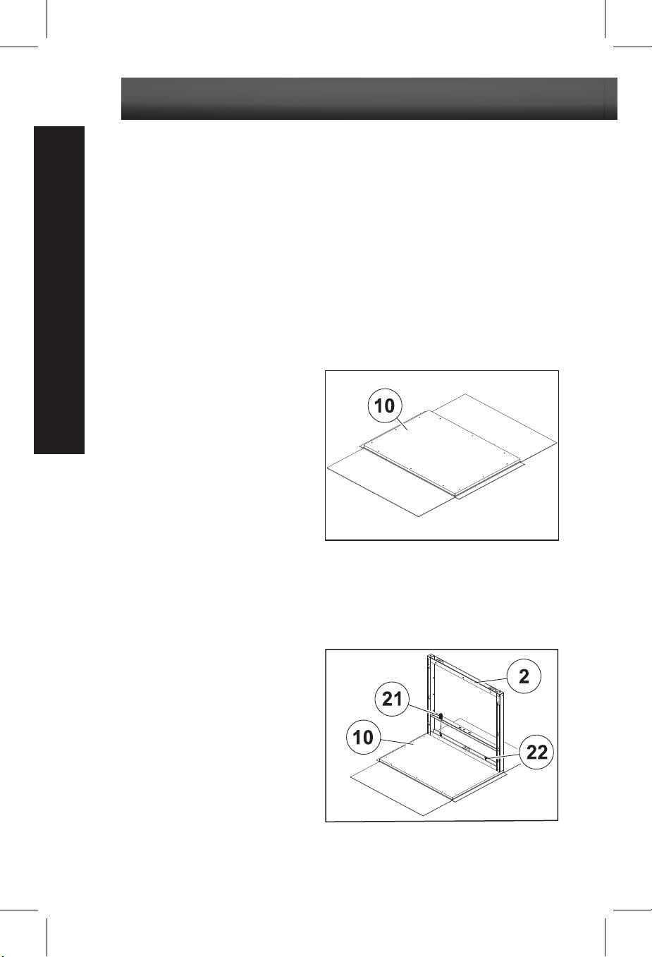
1. Open the cardboard box to remove
the solid wood board (Part 10) and
other parts (see Fig. A).
2. Place the front frame (Part 2) on
the front of the solid wood board (Part
10). Insert two M4 x 10 screws (Part
22) through the front frame and
tighten them using the screwdriver
(Part 21) (see Fig. B).
Note: The screw holes have some tolerance.
Always make sure that the top and sides of the
front frame align with the solid wood board.
Doing so will prevent the need to make
adjustments at the final stage, therefore
reducing time to assemble.
Fig. A
Fig. B
5
ASSEMBLY INSTRUCTIONS
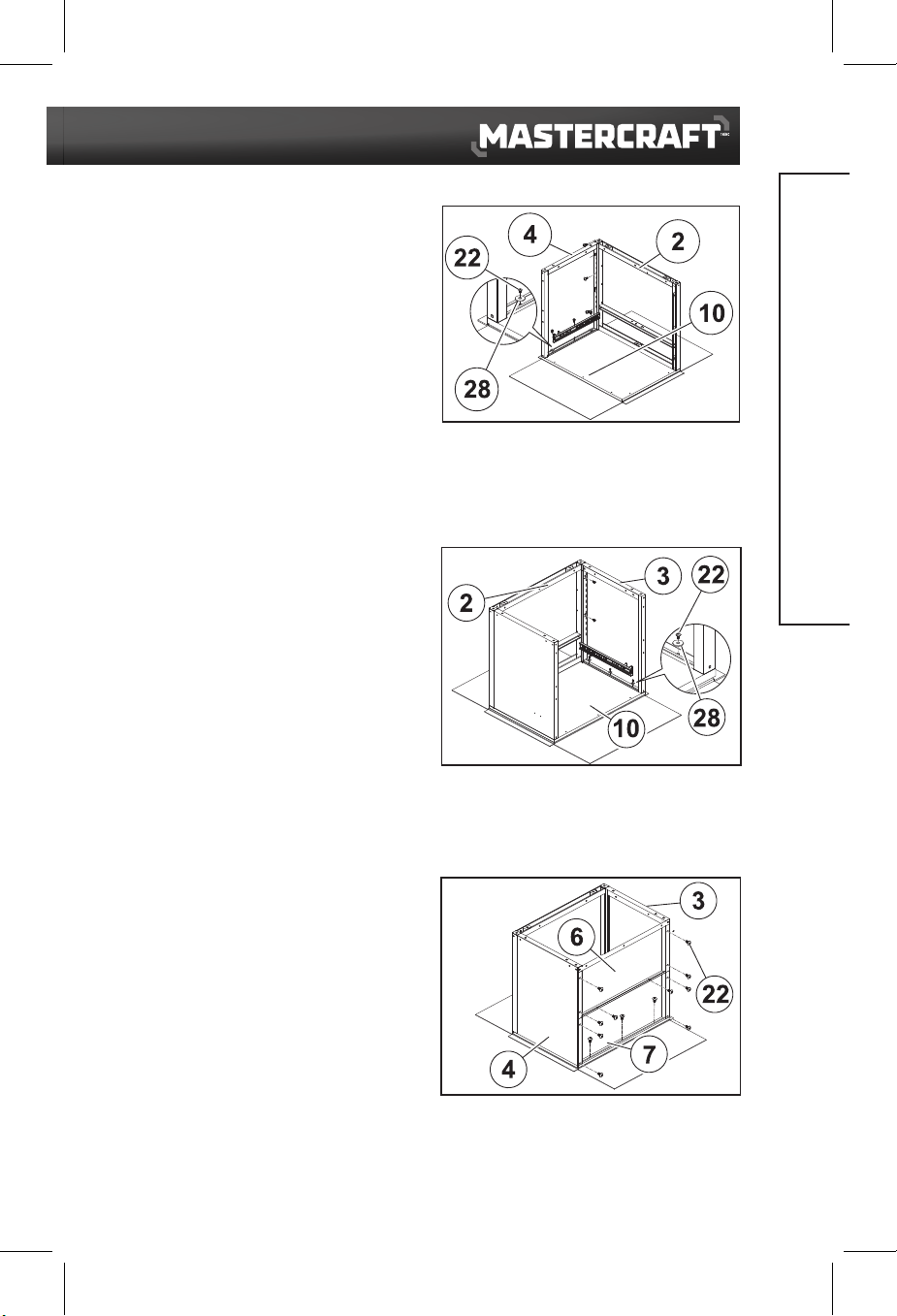
3. Place the left panel (Part 4) on the solid
wood board (Part 10). Make sure the top
of the left panel is aligned with the screw
holes on the front frame (Part 2) and the
solid wood board. Attach the left panel to
the solid wood board and front frame. Add
three washers (Part 28) to the three M4 x
10 screws (Part 22) that will attach the
solid wood board; no washers are
necessary with the three M4 x 10 screws
(Part 22) that attach the front frame.
Tighten the screws using the screwdriver
(Part 21) (see Fig. C).
4. Place the right panel (Part 3) on the
solid wood board (Part 10). Make sure the
top of the right panel is aligned with the
screw holes on the front frame (Part 2)
and the solid wood board. Attach the right
panel to the solid wood board and front
frame. Add three washers (Part 28) to the
three M4 x 10 screws
(Part 22) that will
attach the solid wood board; no washers
are necessary with the three M4 x 10
screws (Part 22) that attach the front
frame. Tighten the screws using the
screwdriver (Part 21) (see Fig. D).
5. Attach the upper back panel (Part 7)
and bottom back panel (Part 6) between
the left panel (Part 4) and right panel (Part
3). Make sure the top of the upper back
panel is on the solid wood board. Line up
the screw holes of the back panels. Insert
13 M4 x 10 screws (Part 22) and tighten
them using the screwdriver (Part 21) (see
Fig. E).
Fig. C
Fig. D
Fig. E
Note: Four screw holes provided at top end of the
upper back panel are reserved for corner protectors.

6
headline bars
continuation tabs
notes
warnings
headline bars
continuation tabs
notes
warnings
model no. 068-0558-4 | contact us 1-800-689-9928
headline bars
continuation tabs
notes
warnings
headline bars
continuation tabs
notes
warnings
model no. 062-3582-8 | contact us 1-800-689-9928
ASSEMBLY INSTRUCTIONS
6. Attach the bottom panel (Part 1) to
the left panel (Part 4), right panel (Part
3), front frame (Part 2) and bottom back
panel (Part 6). Line up the screw holes,
insert eight M4 x 10 screws (Part 22)
into the screw holes and tighten them
using the screwdriver (Part 21) (see Fig.
F).
Note: Only the centre holes of the left panel,
right panel, front frame and bottom back panel
are used for attaching the bottom panel. Other
holes are reserved for corner bumpers.
7. Attach swivel wheels with brakes
(Part 17) and swivel wheels without
brakes (Part 18) to the bottom of the
cabinet. Make sure the swivel wheels
with brakes are installed at the front.
Insert 16 M8 x 18 screws (Part 24) into
the four swivel wheels and tighten them
using the screwdriver (Part 21) (see Fig.
G).
8. Attach the bumpers (Part 19) to the
bottom four corners of the cabinet.
Insert 16 M4 x 18 screws (Part 25) into
the bumpers and tighten them using the
screwdriver (Part 21) (see Fig. H).
Note: After finishing this step, turn the cabinet
to upright position.
Fig. G
Fig. H
Fig. F

7
ASSEMBLY INSTRUCTIONS
9. Align left drawer side panel (Part 12)
and right drawer side panel (Part 13) one
at a time to the back of the drawer front
panel (Part 11). Make sure both drawer
side panels are placed in contact with the
rear of the drawer front panel. Line up the
screw holes of the drawer side panels,
insert four M4 x 8 screws (Part 23) and
tighten them using the screwdriver (Part
21) (see Fig. I).
10. From above, attach drawer base
panel (Part 15) between the two drawer
side panels and to the back of the drawer
front panel (Part 11). Insert six M4 x 8
screws (Part 23) into the drawer base
panel and tighten them using the
screwdriver (Part 21) (see Fig. J).
Note: Do not fully tighten any of the screws until
all screws are partially screwed in.
11. Attach the drawer back panel (Part
14) to the back of the assembled drawer.
Insert seven M4 x 8 screws (Part 23) into
the drawer back panel and tighten them
using the screwdriver (Part 21) (see Fig.
K).
12. Pull out the ball bearing track (1)
towards the front of the slider (2) (see Fig. L).
Note: Do not fully tighten any of the screws until
all screws are partially screwed in.
Fig. I
Fig. J
Fig. K
Fig. L

8
headline bars
continuation tabs
notes
warnings
headline bars
continuation tabs
notes
warnings
model no. 068-0558-4 | contact us 1-800-689-9928
headline bars
continuation tabs
notes
warnings
headline bars
continuation tabs
notes
warnings
model no. 062-3582-8 | contact us 1-800-689-9928
ASSEMBLY INSTRUCTIONS
13. To insert the drawer, pull out the
drawer tracks (1) and ball bearing
tracks (2) as far as possible (see Fig. M).
14. Fit the drawer tracks inside the
track attached to the left panel (Part 4)
and right panel (Part 3). Repeatedly
push and pull the slider until the drawer
is installed in the cabinet. Finally, place
the drawer mat (Part 16) inside the
drawer (see Fig. N).
15. Use four M4 x 10 screws (Part 22)
to attach the magnets (Part 20) to the
front frame (Part 2) (see Fig. 0).
Note: The black plate of the magnet (Part 20)
should be facing the front.
16. Decide the height for the middle
shelf. Place the hooks (Part 26) into the
hook slots and push them down. Place
the middle shelf (Part 9) into the cabinet
at the decided height and push it down
(see Fig. P).
Note: The middle shelf needs hooks at four
corners for support. Make sure the hooks are
placed at the same height.
Fig. M
Fig. N
Fig. O
Fig. P
Tabla de contenidos
Idiomas:
Otros manuales de Almacenamiento de herramientas de MasterCraft


