Mantis E System Manual de instrucciones original

© 2006 Mantis, Div. of Schiller-Pfeiffer Inc. All Rights Reserved.
Edger “E” System
Owners Manual and Safety Instructions

1
Table of Contents
Important Information
A. Introduction
This attachment is fitted with a blade, intended to be used to
edge flower beds, sidewalks, driveways, curbs, etc.
B. Specification.
C. Contents of the package
1. Edge Trimmer Attachment Assembly
2. Handle with handle bracket
3. Wheel assembly with bracket
4. Blade shield with debris flapper
5. Blade
D. Service Information Contact
If you have questions about any topic in this Manual, or for the
name of your local dealer, call 1-800-366-6268 toll free,
Monday - Friday, 8:00 a.m. to 5:30 p.m., Eastern Time, or ask
for Customer Service.
WARNING DANGER
ATTENTION: THIS SYMBOL POINTS OUT
IMPORTANT SAFETY INSTRUCTIONS
WHEN YOU SEE THIS SYMBOL
HEED ITS WARNING! STAY ALERT!
WARNING DANGER
READ & UNDERSTAND THIS MANUAL BEFORE
ATTEMPTING TO OPERATE THIS MACHINE.
TO REDUCE THE POTENTIAL FOR ACCIDENTS,
COMPLY WITH THE SAFETY INSTRUCTIONS IN
THIS MANUAL. FAILURE TO COMPLY MAY RESULT
IN SERIOUS PERSONAL INJURY AND OR
EQUIPMENT AND PROPERTY DAMAGE.
Important Information
Introduction . . . . . . . . . . . . . . . . . . . . . . . . . . . .1
Service Information . . . . . . . . . . . . . . . . . . . . .1
Special Safety Information . . . . . . . . . . . . . . . .1
Safety and Warnings
Safety Decals . . . . . . . . . . . . . . . . . . . . . . . . . .2
General Safety Rules . . . . . . . . . . . . . . . . . . . .3
Assembly Instructions . . . . . . . . . . . . . . .6
Operation . . . . . . . . . . . . . . . . . . . . . . . . . .9
Maintenance . . . . . . . . . . . . . . . . . . . . . .10
Warranties Policy . . . . . . . . . .Back Cover
E. Special Safety Information
MODEL SHAFT TOTAL
LENGTH WEIGHT
330103 24.5” 7.2 lbs.

2
Safety and Warnings
A. Safety Decals
Please pay particular attention to the warning and information
decals found on various parts of this Edger Attachment unit.
They are an important part of the safety system. These decals
must be replaced in time due to abrasion, etc. It is your
responsibility to replace the decals when they become hard to
read. The location of these decals and their part numbers for
ordering are shown below.
WARNING – DANGER
IMPROPER USE OR CARE OF THIS EDGER, OR
FAILURE TO WEAR PROPER PROTECTION
CAN RESULT IN SERIOUS INJURY.
READ AND UNDERSTAND THE RULES FOR
SAFE OPERATION AND ALL INSTRUCTIONS
IN THIS MANUAL.
WEAR EYE AND HEARING PROTECTION,
AND PROPER CLOTHING.
READ AND
UNDERSTAND
OPERATOR’S MANUAL
BEFORE USING!
WARNING!
WARNING! WEAR SLIP-
RESISTANT FOOTWEAR.
MAINTAIN FOOTING AND
BALANCE AT ALL TIMES.
DO NOT STAND ON
SLIPPERY, UNEVEN OR
UNSTABLE SURFACES.
DO NOT WORK IN ODD
POSITIONS OR ON A
LADDER. DO NOT OVER
REACH.
KEEP BYSTANDERS AT
A SAFE DISTANCE.
DANGER ZONE
SURROUNDING THE
OPERATOR. ONLY THE
OPERATOR SHOULD BE
IN THE DANGER ZONE!
WARNING! WEAR EYE
AND EAR PROTECTION
WARNING! THROWN
OBJECTS!
WARNING! ROTATING
CUTTING BLADE!
DANGER! CUTTING
HAZARD! KEEP FEET
AWAY FROM ROTATING
BLADES!
P/N 331180

3
General Safety Rules
1. Never edge while people, especially children or pets are
nearby.
2. Before using, always visually inspect to see that the blade,
blade bolts and cutter assembly are not worn or damaged.
3. Do not start the motor when a bystander is standing in
front of the blade.
4. Do not put hands or feet near or under rotating parts.
5. Never lean over the rotating cutting head. Rocks or other
debris could be thrown into eyes and face and cause
serious personal injury.
6. Use extreme caution when reversing or pulling the edger
toward you
7. Make sure the blade has stopped before crossing surfaces
other than grass and when transporting the edger to and
from the area to be edged.
8. Never operate the edger with defective, missing or
incorrectly fitted guards.
WARNING
WHEN USING ELECTRIC TOOLS, BASIC SAFETY
PRECAUTIONS, INCLUDING THE FOLLOWING,
SHOULD ALWAYS BE FOLLOWED TO REDUCE
THE RISK OF FIRE, ELECTRIC SHOCK AND
PERSONAL INJURY.
Pay particular attention to all sections regarding safety.
Read and understand all these instructions before operating this
product and save these instructions. Be familiar with the
controls and the proper use of equipment.
For safe operations:
1. Keep work area clean.
Cluttered areas and benches invite injuries.
2. Consider work area environment.
Do not expose power tools to rain. Do not use power tools
in damp or wet locations. Keep work area well lit. Do not
use power tools where there is risk of fire or explosion.
3. Guard against electric shock.
Avoid body contact with earthed or grounded surfaces,
e.g. pipes, radiators, stoves, ovens, refrigerators.
4. Keep children away.
Do not let visitors touch the tool or extension cord. All
visitors should be kept away from area. Local regulations
may restrict the age of the operator.
5. Store idle tools.
When not in use, tools should be stored in a dry, high or
locked up place, out of reach of children.
6. Do not force the tool.
It will do the job better and safer at the rate for which it
was intended. Walk, never run.
7. Use the right tool.
Do not force small tools or attachments to do the job of a
heavy duty tool. Do not use tools for purposes not
intended; for example, do not use chain saw attachment to
cut tree limbs or logs.
8. Dress properly.
Do not wear loose clothing or jewelry that can be caught
in moving parts. Long trousers, non-slip gloves and sturdy
work shoes with non-skid soles are recommended when
working outdoors. Wear protective hair covering to contain
long hair.
9. Use protective equipment.
To avoid injury, wear ear, eye protection, face or dust mask
if the operation is dusty. To avoid injury from falling
branches, wear helmet. Eye protection must meet ANSI Z
87.1 requirements.
10. Do not abuse the cord.
Never carry the tool by the cord or yank it to disconnect it
from the socket. Keep the cord away from heat, oil and
sharp edges.
11. Maintain tool with care.
Keep cutting tools sharp and clean for better and safer
performance. Follow instructions for lubrication and
changing accessories. Inspect tool cord periodically and if
damaged, have it repaired by an authorized service facility.
Inspect extension cords periodically and replace, if
damaged. Keep handles dry, clean and free from oil and
grease.
12. Disconnect tools.
When not in use, before servicing and when changing
accessories such as blades, bits and cutters.
13. Remove adjusting keys and wrenches.
Form the habit of checking to see that keys and adjusting
wrenches are removed from the tool before turning it on.
14. Avoid unintentional starting.
Do not carry a plugged in tool with a finger on the switch
trigger. Ensure switch is off when plugging in.
15. Use outdoor extension leads.
When tool is used outdoors, use only extension cords
intended for outdoor use.
16. Important extension cord information:
a. Make sure the extension cords are in good condition
before use.

Length (feet) 1 to 25 26 to 50 51 to 100 101 to 150
Cord gauge (AWG) 18 16 14 12
4
b. Based on the total length of cord that you are going
to use, check the chart to make sure the cord meets the
correct minimum cord gauge (AWG) requirements.
IMPORTANT NOTE:
Using an undersized cord or a larger number cord gauge
(AWG) than recommended in the chart, will cause a loss in
power and overheating of the unit. Using a smaller number
cord gauge (AWG) than recommended in the chart, is
acceptable.
Extension cord chart (minimum cord gauge (AWG))
17. Stay alert.
Watch what you are doing. Use common sense. Do not
operate tool when you are tired, ill or under the influence
of alcohol or other drugs.
18. Check damaged parts.
Before further use of the tool, a guard or other part that is
damaged should be carefully checked to determine that it
will operate properly and perform its intended function.
Check for alignment of moving parts, free running of
moving parts, breakage of parts, mounting and any other
conditions that may affect its operation. A guard or other
part that is damaged should be properly repaired or
replaced by an authorized service center unless otherwise
indicated in this instruction manual. Have defective
switches replaced by an authorized service facility. Do not
use the tool if the switch does not turn it on and off.
Don’t operate the machine with a damaged or excessively
worn cutting device.
WARNING – DANGER
LITTLE WONDER WILL NOT BE RESPONSIBLE
FOR THE FAILURE OF CUTTING DEVICES OR
ACCESSORIES THAT HAVE NOT BEEN TESTED
AND APPROVED FOR USE WITH THIS UNIT.
USE ONLY MANUFACTURER-RECOMMENDED
REPLACEMENT PARTS.
19. The use of any accessory or attachment, other than those
recommended in this instruction manual, may present a
risk of personal injury.
20. Have your tool repaired by a qualified person.
This electric tool conforms to relevant safety requirements.
Repairs should only be carried out by qualified persons
using original spare parts, otherwise this may result in
considerable danger to the user.
21. Keep in mind that the operator or user is responsible for
accidents or hazards occurring to other people or their
property.
22. Work only in daylight or in good artificial light.
23. Keep all guards attached at all times when unit is operated.
24. Always use the shoulder strap.
Adjust the strap for comfort before starting the engine.
25. Secure unit during transport to prevent damage or injury.
26. Machine should not be used in any position that causes
any part to come within 10 feet of overhead electrical
lines. Always be aware of overhead power lines.
27. Always keep a firm grip on both handles when motor is
running: one hand grasps the front “loop” handle while the
other hand grasps the rear handle. Severe injuries can
result if you try to use this machine with only one hand or
with an insecure grip.
28. Thoroughly inspect the area where equipment is to be
used and removed all objects, which can be thrown by the
machine.
29. Always keep area clear of children, pets, and bystanders.
30. Always inspect your unit before each use and ensure that
all handles, guards and fasteners are secure, operating, and
in place. Be sure that all electrical cords are not damaged
or broken.
31. Always maintain and examine your attachments with care.
Follow maintenance instructions given in manual.
32. Don’t attempt to repair any part of the extended reach
“E” system. Have repairs made by a qualified repairman.
See that only original “Mantis” parts are used.
33. Maintain a firm footing and good balance, do not
overreach while trimming. Before you start to trim, check
the work area for obstacles that might cause you to lose
your footing, balance or control of the machine. While
operating the machine always be sure of a safe and secure
operating position especially when using steps or a ladder.
Always be sure of your footing on slopes.

5
WARNING – DANGER
IMPROPER ASSEMBLY OF THIS EQUIPMENT
CAN RESULT IN SERIOUS INJURY. MAKE SURE
TO FOLLOW ALL INSTRUCTIONS CAREFULLY.
IF YOU HAVE ANY QUESTIONS, CONTACT
MANTIS CUSTOMER SERVICE.
34. Always disconnect power cord from power source:
a. Before cleaning blockages.
b. Before checking, cleaning or working on the
cutting portion of the unit.
c. After striking a foreign object: inspect the cutting
part for damage and make repairs before restarting
and operating the unit.
d. If machine starts to vibrate abnormally (check
immediately).
e. Whenever you leave the unit.
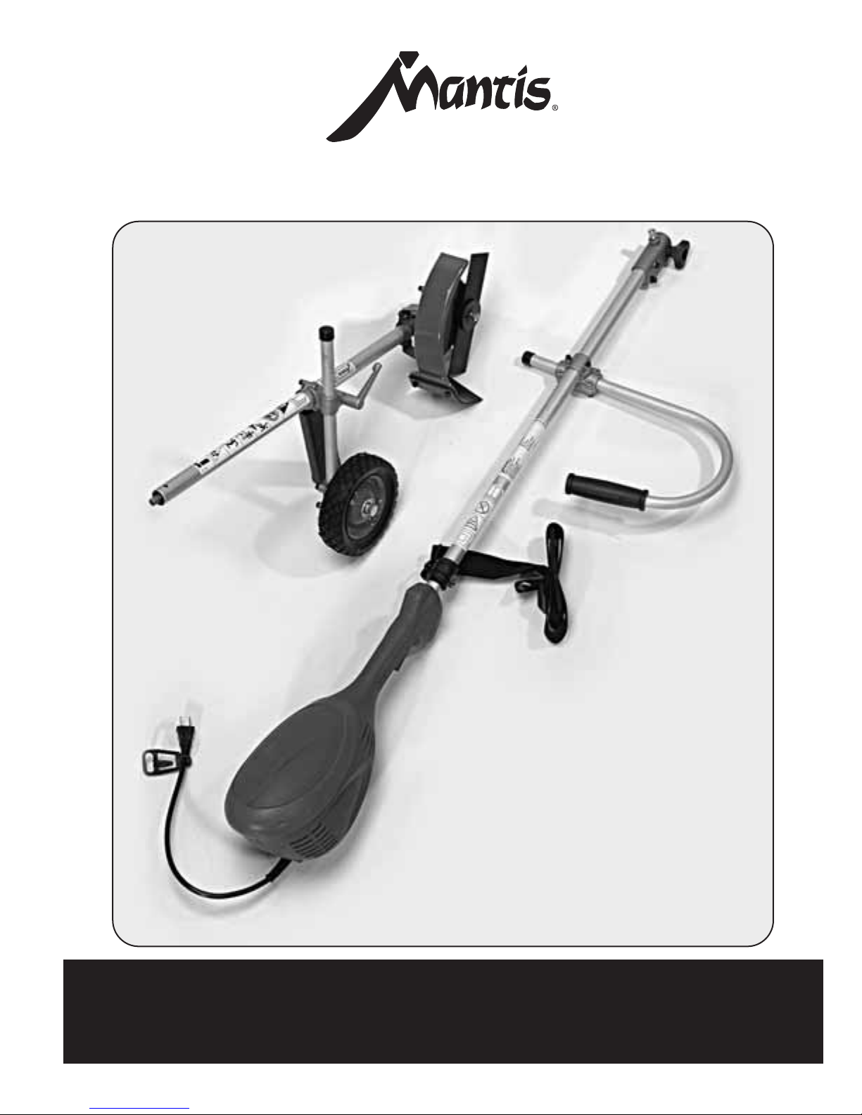
35. Securing the extension cord.
Bend the extension cord about 15 inches from the plug
end. Push that bend through the oblong opening in the
back of the handle. Then loop the bend under the cord
retaining clips as shown. This will prevent the extension
cord from detaching from the hedge trimmer plug.

6
Tools: 9/16" wrench, pin supplied with the unit or
screwdriver
1. Remove the following parts from the Edge Trimmer
Assembly: blade mounting bolt #1 by rotating it
clockwise, clamping plate #2, gear case cover #3,
holding screws #4, and cover #5. (Pictures 1 and 2)
2. Install the blade guard to the gear case aligning 3
mounting holes (Picture 4), then put on cover #5,
align all holes and install 3 screws. (Picture 5)
3. Attach the blade guard to the tube using Clamping
bracket and two screws. (Picture 6)
4. Install gear case cover (Picture 7), blade (Picture 8),
clamping plate (Picture 9), and install blade
mounting bolt with washers. Left thread, rotate
counter-clockwise to tighten. (Picture 10)
5. Lock the gear shaft by putting a pin provided or
screwdriver through the aligned keyholes in the gear
case cover and the gear case. Use a socket wrench to
tighten the blade-mounting bolt. Rotate bolt counter
clockwise to tighten. (Picture 11)
6. Split the bracket, install the wheel assembly to the
tube, and clamp it at the position best for your job,
using two screws. (Picture 12 and 13)
7. You can replace loop handle with the U-shaped
handle that comes with your Edge Trimmer
Attachment.
Assembling the Edge Trimmer
Picture 1 Picture 2
Picture 3 Picture 4
Picture 5 Picture 6
Picture 7 Picture 8
Picture 9
Picture 11
Picture 10
Picture 12 Picture 13
12
5
3
4
3214
5
Gear Case
Blade Guard
Shaft
Clamp
Gear
Case
Cover
Blade
Clamping Plate
Mounting
Bolt
Pin
Bracket
Screws
Cover
4.0-4.5”

7
Check the balance of the assembled unit. The handles and
shoulder harness have been assembled at the factory and set
according to the average sized person. This can be adjusted to
the operator’s preference.
1. Unit handles can be re-adjusted to the operator’s
preference by simply loosening the screws and sliding
handles up or down the shaft. Re-tighten the screws
(Picture 16). The distance between the replacement portion
of the blade and the foremost portion of the guiding handle
should be at least 18" (450mm). (Picture 17)
2. Wheel height can be re-adjusted by loosening clamp lever,
and changing the height of the wheel to achieve desired
cutting depth. (Picture 18) Up-deep cut, down-shallow cut.
Balancing and Depth Adjustment
No tools are required to attach the Edge Trimmer to the power
head assembly.
1. Pull the spring pin up on the adapter of the power head
shaft assembly. (Picture 14)
2. Carefully fit edger drive shaft into adapter, making sure
that male spline of the inner drive shaft engages into the
female spline socket of the power head shaft.
3. When the drive shaft is properly aligned, the spring pin
will drop into the hole on the shaft of the edger attachment.
A click should be heard when completed.
4. Insure two shaft parts are fully engaged by twisting them.
5. Full engagement will prevent shaft rotation.
6. Secure assembly by tightening the knob. (Picture 15)
Attaching the Edger to the
Power Head assembly.
Picture 14 Picture 15
Picture 16
Picture 17 Picture 18
down
up

8
Tools: 9/16" wrench, pin or screwdriver
1. Lock the gear shaft by inserting the pin or screwdriver
through the aligned keyholes in the gear case cover and the
gear case to prevent rotation (Picture 19).
2. Hold the pin or screwdriver in place and remove bolt by
turning it clockwise (Picture 20), then remove clamping
plate (Picture 21), and worn blade (Picture 22).
3. Place new blade (Picture 23), re-install clamping plate
(Picture 24), and bolt (Picture 25). Use wrench to tighten
the blade-mounting bolt. If bolt is worn or damaged use a
new one. Replace worn or damaged blade and bolts in
sets to preserve balance.
Replacement Blade Installation
Picture 19 Picture 20
Picture 23 Picture 24
Picture 25
Picture 21 Picture 22
WARNING – DANGER
BE SURE UNIT IS UNPLUGGED BEFORE
MAKING ANY ADJUSTMENTS.

9
1. Clean.
2. Lubricate for rust prevention.
3. Store indoor.
Storage
1. With both hands on the handles, push lockout trigger
button with your thumb first, and then squeeze trigger.
Start edging when blade rotates at full RPM, by
lowering the blade gently into the ground.
2. Thoroughly inspect the surface were the equipment is to be
used and remove all stones, sticks, wires, bones and other
foreign objects.
3. Before edging, water the area to soften the ground to make
edging easier.
4. Plan to edge regularly to make it easier to keep a neat edge
and to avoid making more then one pass.
5. Don’t force the blade. Only move forward as the blade will
allow.
6. Do not use Edger Attachment to make a new groove into
hard ground!
7. You can use the V-notch to indicate postion of the
blade tip.
Trimming Techniques
Lockout Trigger Button Trigger
V-notch to indicate
the position of the
blade tip
V-notch in the
blade guard
Blade
Otros manuales para E System
2
Tabla de contenidos
Otros manuales de Arista de Mantis