Magic-Pro MP-VIP4 Manual de usuario

MP-VIP4
Motherboard
User’s Manual
Product Name:MP-VIP4
Manual Revision:English,3.00
Release Date:Feb 10, 1999

POST-CONSUMER
RECYCLED PAPER
Federal Communications Commission Statement
This device complies with FCC Rules Part 15. Operation is subject to the following two
conditions:
wThis device may not cause harmful interference
wThis device must accept any interference received, including interference that may
cause undesired operation.
This equipment has been tested and found to comply with the limits for a Class B digital
device, pursuant to Part 15 of the FCC Rules. These limits are designed to provide
reasonable protection against harmful interference in a residential installation. This equipment
generates, uses and can radiate radio frequency energy. If this equipment is not installed and
used in accordance with the manufacturer's instructions, it may cause harmful interference to
radio communications. However, there is no guarantee that interference will not occur in a
particular installation. If this equipment does cause harmful interference to radio or television
reception, which can be determined by turning the equipment off and on, the user is
encouraged to try to correct the interference by one or more of the following measures:
wReorient or relocate the receiving antenna.
wIncrease the separation between the equipment and receiver.
wConnect the equipment to an outlet on a circuit different from that to which the
receiver is connected.
wConsult the dealer or an experienced radio/TV technician for help.
The use of shielded cables for connection of the monitor to the graphics card is required to
assure compliance with FCC regulations. Changes or modifications to this unit not expressly
approved by the party responsible for compliance could void the user's authority to operate
this equipment.
Canadian Department of Communications Statement
This digital apparatus does not exceed the Class B limits for audio noise emissions from
digital apparatusses set out in the Radio Interference Regulations of the Canadian
Department of Communications.
Manufacturer's Disclaimer Statement
The information in this document is subject to change without notice and does not represent a
commitment on the part of the vendor. No warranty or representation, either expressed or implied,
is made with respect to the quality, accuracy or fitness for any particular purpose of this document.
The manufacturer reserves the right to make changes to the content of this document and/or the
products associated with it at any time without obligation to notify any person or organization of such
changes. In no event will the manufacturer be liable for direct, indirect, special, incidental or
consequential damages arising out of the use or inability to use this product or documentation, even
if advised of the possibility of such damages. This document contains materials protected by
copyright. All rights are reserved. No part of this manual may be reproduced or transmitted in any
form, by any means or for any purpose without expressed written consent of it's authors. Product
names appearing in this document are mentioned for identification purposes only. All trademarks,
product names or brand names appearing in this document are registered property of their
respective owners.
Copyright Magic-Pro Computer Co., LTD.
All rights reserved
Author : Raymond Liu
Printed in Taiwan Feb 1999

I
Contents
Chapter 1: Introduction---------------------------------------1
Features-------------------------------------------------------------------------1
CPU------------------------------------------------------------------------1
Chipset--------------------------------------------------------------------1
L2 Cache------------------------------------------------------------------1
Main Memory-----------------------------------------------------------1
BIOS------------------------------------------------------------------------2
I/O Function-------------------------------------------------------------2
Other Functions---------------------------------------------------------2
Mainboard Setting for Pentium MMX-200-----------------------------3
Chapter 2: Hardware Setup----------------------------------4
CPU VCORE Voltage Setting----------------------------------------------4
JP3: CPU VCore Voltage Setting-----------------------------------4
AGP Driver for Win95 Installation--------------------------------------5
Requirement-------------------------------------------------------------5
Installation Procedure-------------------------------------------------5
Intel Pentium MMXÐ166/200/233 CPUs------------------------------6
AMD K6 CPU Settings------------------------------------------------------7
AMD K6 Ð 166/200/233/266/300 and K6-2 266 CPUs-------7
AMD K6-2 Ð 250/300/333/350/380/400 CPU Settings------------8
Cyrix/IBM 6x86MX Ð PR200/233/266 CPUs-------------------------9
IDT C6 Ð 200/225 CPUs--------------------------------------------------10
Intel Pentium/AMD K5 Ð 133/166/200 CPUs----------------------10
System Memory Configuration-----------------------------------------11
Jumper Settings-------------------------------------------------------------11
JP2: Clear CMOS Data----------------------------------------------11
JP17, JP18: CPU Dual/Single Voltage Select------------------12
SW1: 4~6: Bus Ratio Select-----------------------------------------12
JP1, JP6: SDRAM Clock Setting-----------------------------------13

ContentsII
JP7, JP8: Chipset Clock Settings----------------------------------13
IDE LED Activity Light: (J1 pin1Ð4)------------------------------14
Infrared Port Module Connector (J1 pin6Ð10)-----------------14
J1 pin12, 13: ATX Power Button----------------------------------14
J1 pin14, 15: Reserved-----------------------------------------------14
Speaker Connector (J2 pin1Ð4)------------------------------------14
Reset Switch (J2 pin5, 6)---------------------------------------------14
Power LED and Keylock Switch (J2 pin8Ð12)------------------14
Turbo LED (J2 pin14, 15)--------------------------------------------15
USB: USB Connector------------------------------------------------16
J1 Switch Signal Summary-----------------------------------------17
J2 Switch Signal Summary-----------------------------------------18
Chapter 3: BIOS Setup---------------------------------------19
Standard CMOS Setup----------------------------------------------------20
BIOS Features Setup-------------------------------------------------------22
Chipset Features Setup---------------------------------------------------25
Power Management Setup-----------------------------------------------28
PnP/PCI Configuration Setup------------------------------------------30
Load Setup Defaults-------------------------------------------------------33
Integrated Peripherals----------------------------------------------------34
Supervisor/User Password----------------------------------------------37
IDE HDD Auto Detection------------------------------------------------38
Save & Exit Setup----------------------------------------------------------38
HDD Low Level Format--------------------------------------------------38
Exit Without Saving-------------------------------------------------------39

Introduction 1
Chapter 1
Introduction
Features
CPU
1. Supports Intel Pentium P54C/MMX (P55C) CPUs at 133
~ 233 MHz;
2. Supports Cyrix/IBM 6x86(L) CPUs at PR133+~ PR250+
MHz and 6x86MX/MII CPUs at PR166+~ PR350+MHz;
3. Supports AMD K5: PR133 ~ PR200MHz, AMD K6: 166 ~
300MHz, and AMD K6-2: 250 ~ 400MHz;
4. Suports IDT C6: 200 ~ 225MHz;
5. Provides SOCKET 7 ZIF Socket;
6. Supports 66/75/83/95/100/112/124/133 MHz CPU clock;
7. Supports CPU voltage auto detect and switching circuit.
Chipset
1. VIA Apollo MVP3 chipset;
2. PCI Rev 2.1 and APM1.1/1.2 compliant.
L2 Cache
1. Onboard supports 512k or 1MB write back cache with
Pipelined Burst SRAMs.
Main Memory
1. Memory range from 4MB (minimum) to 768MB
(maximum) with DRAM Table Free configurations;
2. Supports Fast Page Mode/EDO/SDRAM;
3. Supports 2pcs 72pin SIMM sockets and 2 pcs of 168pin
DIMM sockets (3.3V unbuffered type).

2
BIOS
1. AWARD Plug and Play BIOS;
2. Supports Advanced Power Management Function;
3. Flash Memory for easy upgrade.
I/O Function
1. Integrated USB (Universal Serial Bus) controller with
two USB ports;
2. Supports 2 IDE channels with 4IDE devices (including
120MB IDE floppy);
3. Provides PCI IDE Bus Master function;
4. One floppy port;
5. Two high speed 16550 FIFO UART ports;
6. One parallel port with EPP/ECP/SPP capabilities;
7. PS/2 mouse connector;
8. Infrared module connector.
Other Functions
1. AT Form Factor with 22cm x 24cm;
2. 3 PCI Master slots, 3 ISA slots, and 1 AGP slot;
3. Supports SCSI/CD-ROM Boot function.
Note: 1. Make sure that the SDRAM module not only has
to be 168 pin DIMM but designed for 3.3V
unbuffered SDRAM as well. Double check with
the SDRAM supplier before install any
SDRAMs. The mainboard manufacturer has no
obligation to any damage of the board by using
the incorrect specification of SDRAM.
2. Do not mix EDO and SDRAM together for the
system stability.
3. For 100MHz CPU environment, the SDRAM
must compliant PC-100 specification,
otherwise, the system maybe unstable.

Introduction3
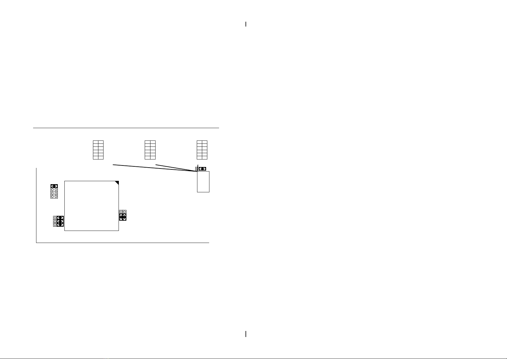
Mainboard Setting for Pentium MMX-200
The default settings of the following figure is for the INTEL
Pentium MMX-200, Vcore: 2.8V.
ISA3 ISA2 ISA1
PCI2 PCI1
PCI3
W83877F/TF
MS1 KB1
AT Power Con
ATX Power Con
VT82C586B
SIMM1
SIMM2
DIMM1
DIMM2
IDE2
IDE1
LPT
FDC Con
COM2COM1
FLASH BIOS
Li
BAT
Clock
Gen
1
JP2
1
CPU
FAN
PCI SLOTS
ISA SLOTS
MMX-200 CPU
Pipelined
SRAM
Pipelined
SRAM
USB
AGP Slot
VIA
MVP3
1
2
3
4
5
6
ON
JP3
78
12
J2 HD/LED IR PWR/SW
J1 T/LEDKEYLOCKRESETSPK
TAG
SW1
Off On
On
Off On
Off
12
1516
1
JP1
1
JP6
JP7
JP8
1
JP17
JP18
Figure 1–1. MP-VIP4 Motherboard Layout
Note: Double Check JP1, JP6 ~ JP8 if system can not be
boot up.
4
Chapter 2
Hardware Setup
CPU V
CORE
Voltage Setting
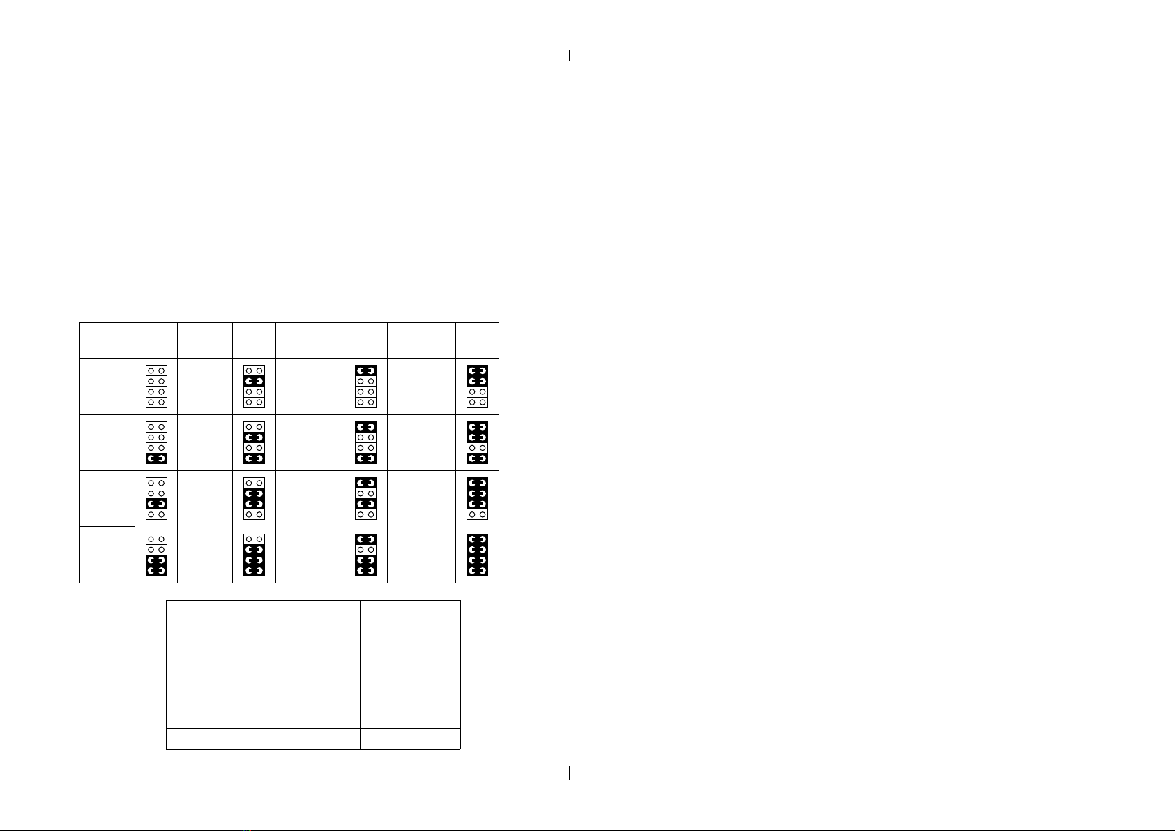
JP3: CPU V
Core
Voltage Setting
3.1V
3.5V
Pentium (P54C)
6x86
K5
VCore
Voltage
3.0V 3.4V
2.9V
K6Ð166/200
6x86MX (MII)
3.3V
IDT C6
2.8V
MMX, 6x86L
3.2V
K6Ð233
VCore
Voltage
2.4V
2.0V
VCore
Voltage
2.5V
2.6V
2.7V
2.1V
2.2V
K6-266
(or higher)
K6-2
2.3V
VCore
Voltage
JP3 JP3 JP3 JP3
CPU Type VCore
Pentium (P54C), 6x86, K5 3.52V
MMX (P55C), 6x86L 2.8V
IDT C6 3.3V
K6-166/200, 6x86MX/MII 2.9V
K6-233 3.2V
K6-266 (or higher), K6-2 2.2V

Hardware Installation 5
Note: 1. Refer to the table above to choose the correct
voltage for the CPU everytime that you install a
CPU.
2. Make sure that your JP3 is matched with the
CPU voltage, otherwise will damage the CPU or
make the system unstable.
3. When the new CPU is announced and is not
listed on this manual, please refer to the above
table, select the correct voltage setting for it.
AGP Driver for Win95 Installation
Requirement
¥ Microsoft Windows95OSR2.1 (OSR2.0 with USB upgrade)
¥ Apollo MVP3 AGP VxD Driver
¥ AGP VGA Card with Driver
¥ DirectX 5.0 (or higher) DDK or SDK
Installation Procedure
Step1 Go to the next step if you are running
Win95OSR2.0/2.1, and if not, install Windows95
4.00.950B or later version
Step2 Install USBSUPP.EXE program (USB upgrade)
Step3 Install Microsoft DirectX 5.0 (or higher) DDK or
SDK
Step4 Install AGP driver for Windows95
Step5 Install Apollo MVP3 AGP VxD Driver, run
ÒSETUP.EXEÓ program
To make sure if the Apollo MVP3 AGP driver is properly
installed, boot up the system and run the ÒRegeditÓ to check
if the following path with VIAGARTD exists:
6
ÒHKEY_LOCAL_MACHINES\System\CurrentControlSet\
Services\VxDÓ.
Follow the below procedure to check if the AGP driver is
capable to activate:
1. Activate ÒControl Panel,Ó
2. Click ÒDirectX,Ó
3. Click ÒDirectDraw,Ó and
4. Check if there are some values in ÒBitÓ and ÒOverlays.Ó
If there are some values, the AGP is able to activate.
Intel Pentium MMX–166/200/233 CPUs
1
Off
2
On
3
On
4
5
On
On
6
Off
ON
1
2
3
4
5
6
ON
1
2
3
4
5
6
ON
MMX–166
Off
On
On
Off
On
Off
MMX–200
Off
Off
Off
On
On
Off
MMX–233
Intel MMX CPUs
JP3
78
12
SW1
(2.8V)
1
JP1
1
JP6
JP7
JP8
1
JP17
JP18
Figure 2–1. CPU Type Configuration
Tabla de contenidos
Otros manuales de Placa madre de Magic-Pro


Manuales populares de Placa madre de otras marcas


Telit Wireless Solutions
Telit Wireless Solutions SL869-3DR Manual de usuario

Gigabyte
Gigabyte GA-9IVDT Manual de usuario

Texas Instruments
Texas Instruments ADS8372EVM Manual de usuario

Commell
Commell MS-C73 Manual de usuario

IBT Technologies
IBT Technologies MB860 Manual de usuario

Nvidia
Nvidia TEGRA DG-04927-001_V01 Manual de usuario


