Luminex GigaCore Series Manual de usuario
USER MANUAL
GIGACORE PRODUCT FAMILY
GigaCore 10
THANKS FOR CHOOSING LUMINEX
Description: User Manual GigaCore 10.
REVISION: 20200204-REV 2.8.4

2

CONTENTS
1. INSTALLATION.................................................................... 4
1.1 Mounting the device ..............................................................4
Rack mount...................................................................4
Rack mount - two devices...................................4
Truss mount .................................................................5
Wall Mount ...................................................................6
1.2 Power up the device ...............................................................6
1.3 Description....................................................................................7
1.4 LED Indicators..............................................................................8
1.5 Connecting to the web interface....................................8
1.6 Reset ..............................................................................................8
2. GIGACORE FEATURES EXPLAINED................................ 9
2.1 RlinkX ..............................................................................................9
2.2 Groups .........................................................................................10
2.2 MultiLinkX................................................................................... 10
3. CONFIGURATION............................................................12
3.1 Connecting to the web interface................................. 12
3.2 Status Page.................................................................................12
3.3 Global Page................................................................................13
3.4 RlinkX ...........................................................................................17
3.5 Groups........................................................................................... 18
3.6 PoE ..................................................................................................20
3.7 Profile Manager .......................................................................22
4. RESET ...............................................................................24
4.1 Reset ............................................................................................24
4.2 Reload Default..........................................................................24
4.3 Factory Reset.............................................................................25
5. TECHNICAL SUPPORT....................................................25
3

1. INSTALLATION
1.1 Mounting the device
GigaCore 10 is a device that can be mounted in a truss as well as
in a rack. Please read the following instructions to make sure the
device is mounted and secured correctly.
RACK MOUNT
In case you want to mount your GigaCore 10 in a standard 19-inch
rack, you must attach the included mounting ears. Connect the
longest ear (A) to the right-hand side of the device with 4 screws,
re-used from the device. Attach the shorter ear (B) to the left-hand
side again with the 4 screws.
RACK MOUNT TWO DEVICES
In case you want to mount two GigaCore 10 devices in a standard
19-inch rack you can mount the two devices together. This is a way
to save space as the two devices will only consume a single row in
your 19-inch rack.
Connect the shortest ear (C) to the left-hand side of the first device
with 4 screws, re-used from the device. Attach the other shortest
ear (D), delivered with the second device, to the right-hand side
of the second device, again with 4 screws. Use a pair of mounting
brackets (E) to connect the two devices in the middle on the front
side. Use a second pair of mounting brackets (E), delivered with
the second device, to connect the devices at the rear. Each pair of
brackets must be mounted with 2 screws.
B
A
C
E
E
D
4
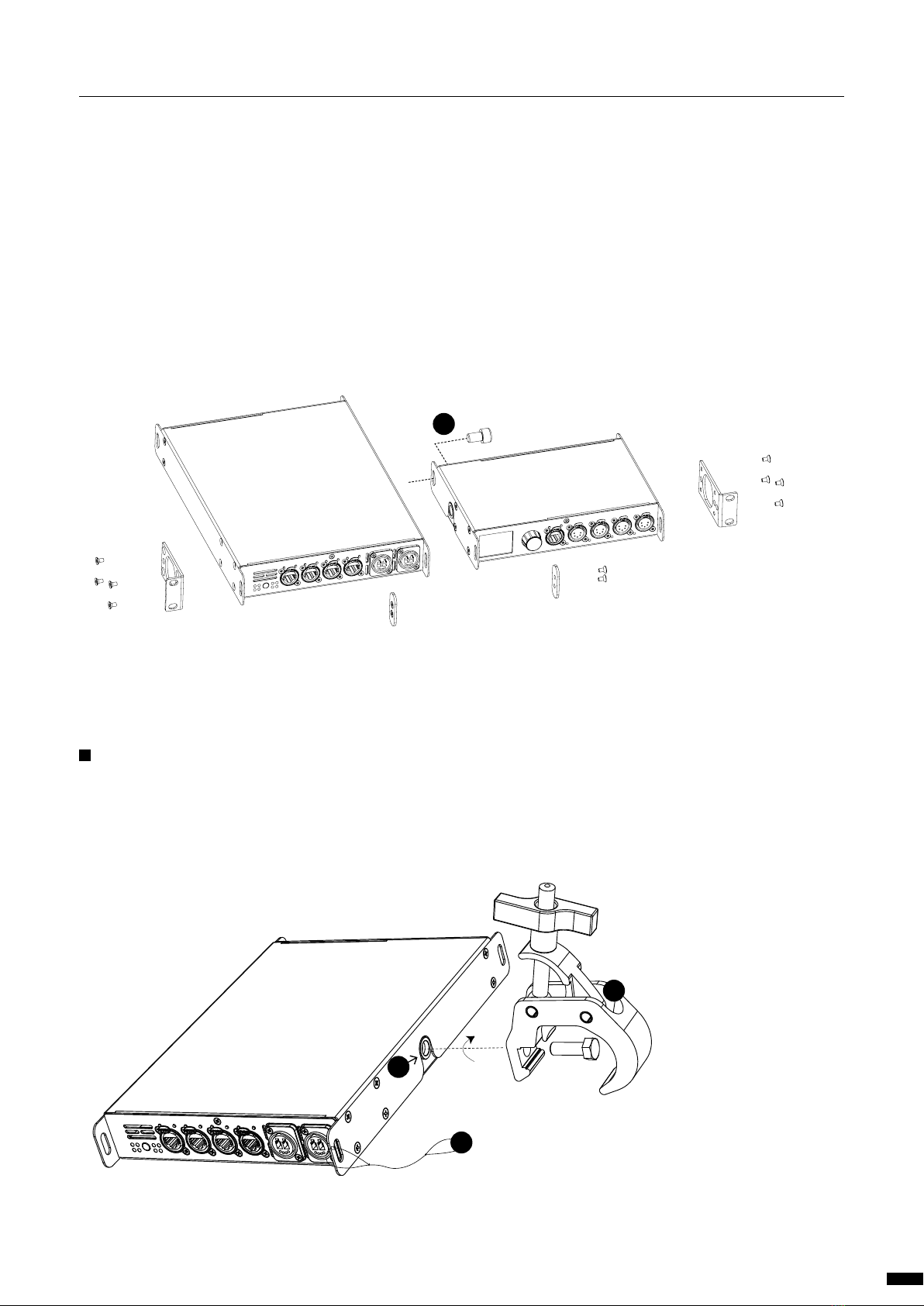
To combine a GigaCore 10 device with a Luminex half 19” device,
style LumiNode 4, the mounting procedure differs a little.
The bolt (F), not included, replaces the rear couplers at the rear
side of the devices. Use the correct bolt, M10x20, with a screw wire
no longer as 20mm. You can order this part from Luminex (Part
Number: R 90 01042)
Screw the bolt, through the LumiNode 4 back ear, into the side
M10 insert and tighten it. The rest of the mounting procedure re-
mains the same.
TRUSS MOUNT
To mount a GigaCore 10 in a truss, you must attach a M10 clamp
(G) to the M10 insert (H). After that, you can mount the clamp to
the truss bars. Please also secure the device by attaching a safety
line directly to the truss bars as well (I).
F
G
I
H
5
1 | INSTALLATION / 1.1 MOUNTING THE DEVICE
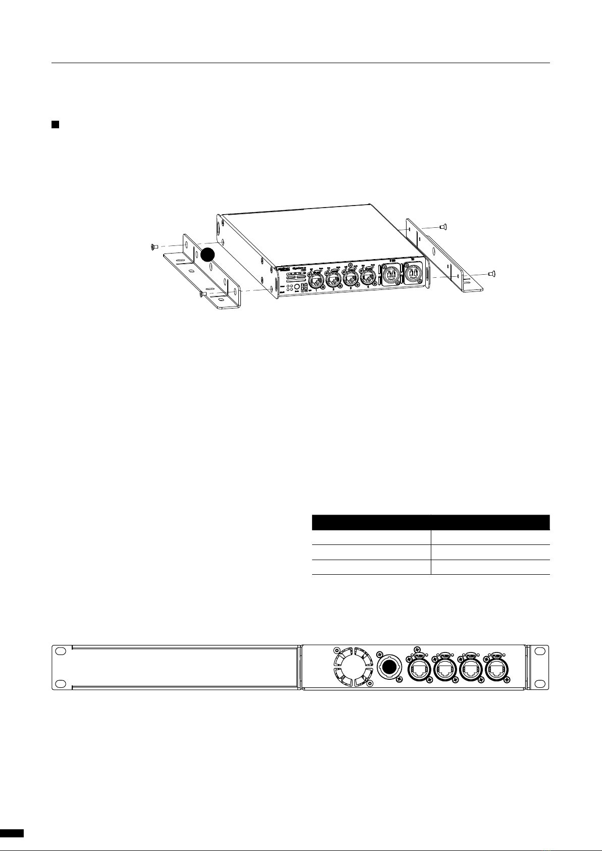
1.2 Power up the device
Power-up the device with a power cable with Neutrik powerCON
TRUE1 connection (J) (please contact your local dealer if you don’t have
a suitable power cable on hand). The device will automatically switch
on. To shut it down after use, just un-plug the power cable again.
After connecting the power cable correctly, by default the power LED
indicator on the front panel will light up in green.
The GigaCore 10 requires standard AC power distribution from 100-
240VAC, 50/60Hz. Current required depends on the model.
The mating Neutrik® powerCON® TRUE1 connector is supplied;
however, you will need to purchase or construct a cable appropriate
for your application.
When installing a new connector please refer to the following wire
colour code reference:
WIRE* CONNECTION
Green/Yellow AC Ground
Blue AC Neutral
Brown AC Line
* International (Harmonised) Standard
J
WALL MOUNT
To mount a GigaCore 10 on the wall, you must attach the wall
mount brackets (A) (LU_10_00126). Connect the brackets with 4
screws, re-used from the device.
A
6
1 | INSTALLATION / 1.1 MOUNTING THE DEVICE / 1.2POWER UP THE DEVICE
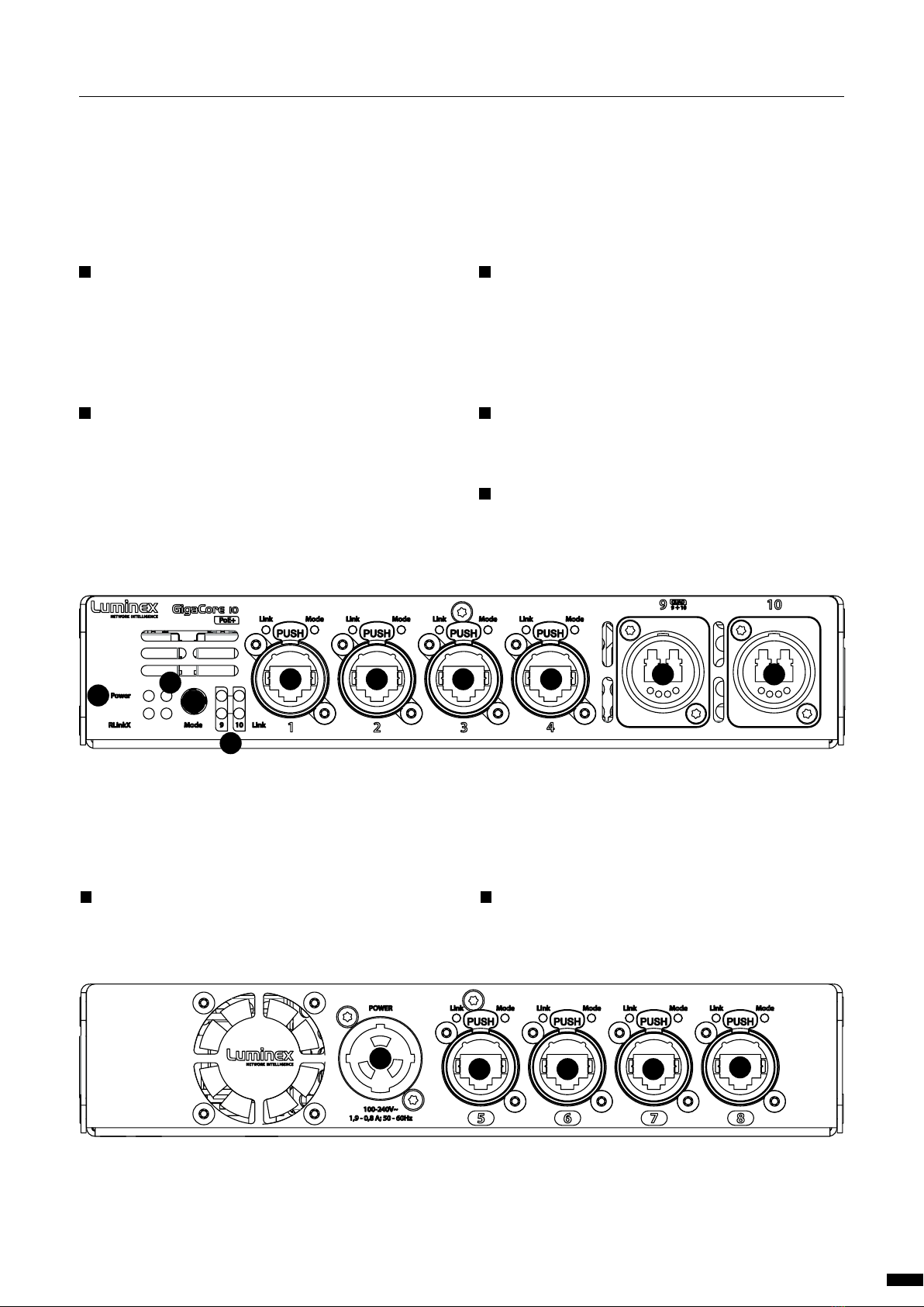
1.3 Description
1.3.1 Front Panel
A STATUS LEDS:
Power: Indicates the status of the power supply.
PoE: Indicates the status of the PoE functionality and the PoE
supplies (GigaCore 10 with PoE only).
RLinkX: Indicates the RLinkX status.
B MODE:
Mode LED: Indicates the selected state for the port Mode LEDs
(see the“LED indicators”section for more details).
Mode button: Use this button to browse through the different
states for the port Mode LEDs.
C OPTICAL PORT LEDS:
2x Optical Port Mode: According to the selected state, the
LED will show different colours.
2x Optical Port Link/Speed: Shows the current speed and
link activity of a port.
D ETHERCON PORTS:
4x EtherCon 10/100/1000Mbs port.
E OPTICAL FIBRE:
1x Quad core or 2x Duo core fibre optic connector.
1.3.1 Rear Panel
F POWER:
1x Neutrik powerCON TRUE1 inlet.
G ETHERCON PORTS:
4x EtherCon 10/100/1000Mbs port.
AB
B
C
D D
FG G G G
D D E E
7
1 | INSTALLATION / 1.3 DESCRIPTION

1.5 Connecting to the web interface
The default GigaCore IP address is displayed at the rear of the
unit. Set your computer with a compliant IP address (do not
use the same IP address!).
Connect your computer to the GigaCore with a network cable.
Launch your favourite web browser.
Type the IP address of the switch in the address field followed
by enter .
PLEASE KEEP IN MIND THE WEB INTERFACE OF A SWITCH
CAN ONLY BE REACHED THROUGH A PORT ASSIGNED IN THE
MANAGEMENT GROUP (FROMTHE SWITCHYOU’RE CONNECTED
TO, OR FROM ANOTHER SWITCH THROUGH AN ISL PORT). YOU
NEED AT LEAST ONE PORT ASSIGNED TO THE MANAGEMENT
GROUP IN YOUR ENTIRE NETWORK TO REACH THE WEB INTER-
FACE OF ALLYOUR GIGACORE SWITCHES
FACTORY DEFAULT ALL PORTS ARE ASSIGNED TO THE MANAGE-
MENT GROUP.
1.6 Reset
Sometimes it can come in handy to reset the device. To do this,
press and hold the mode button for 10 seconds. Once the four
status LEDs blink red, release the button. This will reset all settings
to default. The user profiles will be preserved though.
For more detailed information on how to reset the device and
what reset options are available please check chapter 4 of this
manual.
1.4 LED indicators:
The LED indicators of the GigaCore 10 and GigaCore 10 with PoE show
the following statuses:
SWITCH LED COLOUR DESCRIPTION
Power (General status
LED)
Green All OK
Green blink Unit is writing to the flash.
Do not disconnect power
Orange Temperature warning
Red blink Temperature or Fan error
Red/Green
blink
The unit is flashing
new firmware. Do not
disconnect power
PoE LED (GigaCore 10
with PoE only)
Green Internal PoE supply OK.
PoE functionality OK
Red blink PoE supply or PoE
functionality error
RLinkX LED Green RLinkX is active
PORT LED STATUS DESCRIPTION
Link Off No Link
Green Gigabit connection
Orange 10/100 Mbps connec-
tion
Blink Activity
With the use of the mode button, the user can get all the necessary
information immediately. Press the mode button to browse through
the different states.
STATE MODE
LED
PORT
MODE
LED
DESCRIPTION
Groups White Group
Colour
The LED Colour
indicates the group
assignation of the port
RLinkX Blue Blue Indicates a redundant
port
MultiLinkX Magenta Magenta MultiLinkX is enabled
on this port
White MultiLinkX is active on
this port
PoE Yellow Yellow PoE is activated on this
port
Orange Port is sourcing PoE to
a device
Red Error with PoE
Dark Mode Off Off All port LEDs are
switched off. Switch
status LEDs remain
available.
8
1 | INSTALLATION / 1.4 LED INDICATORS / 1.5 CONNECTION WEB INTERFACE / 1.6 RESET
2.GIGACORE FEATURES EXPLAINED
The GigaCore range of switches offers many unique features
which greatly simplify your everyday job.
These features will be explained on the following paragraphs.
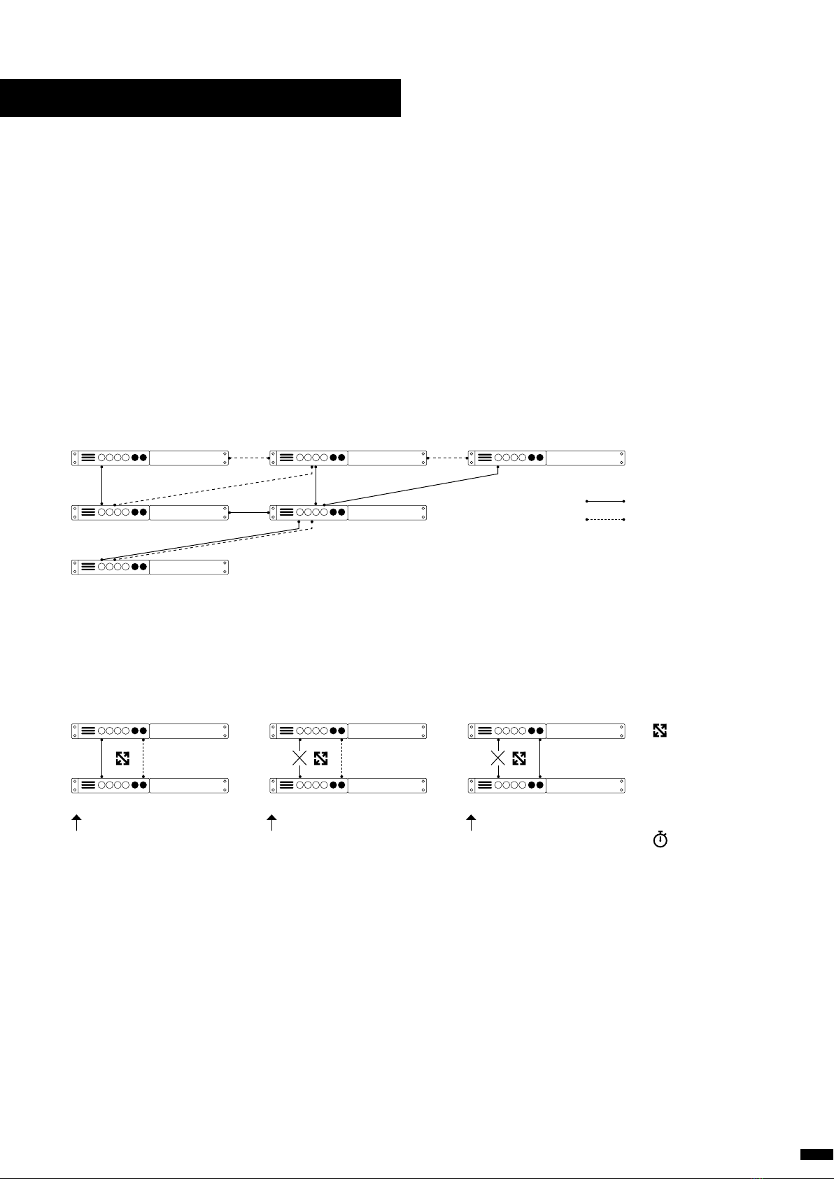
2.1 RlinkX:
RLinkX, which stands for Redundant Link by LumineX, is an automat-
ed system to easily create redundant paths between your GigaCore
switches. Switches automatically create active and redundant paths,
providing an effortless method to create safe networks.
If one of the active paths fails, the switches will enable a redundant
path in a seamless manner.The recovery time is between 20 and 40ms.
By default, all GigaCore ports have RLinkX enabled, which means you
can interconnect any GigaCore switch between each other. All redun-
dant paths will be created automatically by the switches, no need for
configuration.
To create a redundant path with RLinkX, simply connect a minimum
of two links between two GigaCore switches. The blue RLinkX LEDs of
the connected ports will turn on, indicating the redundancy is active
and available.
If your port’s RLinkX LED turn off, you have lost one of your redundant
paths.
User connects two switches with
two links. The switches automati-
cally create a backup link.
Active link becomes unavailable Backup link becomes active
automatically
Active path
Backup path
RlinkX
20-40ms
9

2.2 Groups (VLANs)
The groups function allows the user to segment the network into sev-
eral virtual networks (VLANs). The main benefit of this function is that
no group will affect the other ones, on protocol level.
The user can create several groups on the network, and each device
included in a group will be able to communicate with devices in this
group only. This will result in a better bandwidth, and no protocol con-
flict.
Three groups have been created in the illustration to the right: Red,
Green and Blue. Each device included in each group can communi-
cate with devices from the same group. Thus, the sound console and
the sound processor can talk to each other, without being flooded by
packets streamed by the two other groups.
The GigaCore switches offer 20 groups, to which the user can assign
any of the ports. Two devices must be part of the same group to com-
municate.
When more than one switch is used in a group-based network, the
Inter Switch Link group (ISL Group 0) must be used to forward the
group’s packages between switches.
2.3 MultiLinkX:
Most of the time, a redundant link set with RLinkX between two Gi-
gaCore switches will be good for the everyday event. A 1000Mbps link
is more than enough for most of the current applications. However,
it can happen that you’ll need to transfer a larger amount of data be-
tween the switches.
For example four video transmitters are transmitting four video
streams to each dedicated receiver. Each stream requires a throughput
of 400Mbps, which represents 1600Mbps in total.
However, only one link is active between the switches, as the oth-
er link is used as redundant link. So, a maximum of 1000Mbps data
transfer can be achieved on this link. In the above example, we need
1600Mbps of throughput to transfer all four video streams between
the switches.
This is not enough, the link between the switches will create a bottle-
neck, resulting in data loss or data delay. The video streams won’t be
delivered in time and will create lag in the video output.
The solution? MulitiLinkX!
MultiLinkx enables you to gather several links together and turn them
into one virtual link (link aggregation). This provides you with more
bandwidth between the switches, and thus more throughput. Multi-
LinkX can accept a maximum of 16 ports per aggregation, and up to 8
aggregations can be created on a switch.
Light Over IP Converter
Light Over IP Console
Sound Over IP Processor
Sound Over IP Console
Video Over IP Out
Video Over IP Out
Inter Switch Links (ISL)
Rx: 400Mbps
Tx: 400Mbps
Rx: 400Mbps
Tx: 400Mbps Tx: 400Mbps
1000Mbps
Rx: 400Mbps Rx: 400Mbps
Tx: 400Mbps
Rx: 400Mbps Rx: 400Mbps Rx: 400Mbps Rx: 400Mbps
Tx: 400Mbps Tx: 400Mbps Tx: 400Mbps
1000Mbps
+1000Mbps
Tx: 400Mbps
10
2 | GIGACORE FEATURES EXPLAINED / 2.2 GROUPS / 2.3 MULTILINKX
Otros manuales para GigaCore Series
1
Este manual sirve para los siguientes modelos
6
Tabla de contenidos
Otros manuales de Hardware de red de Luminex


Manuales populares de Hardware de red de otras marcas

Matrix Switch Corporation
Matrix Switch Corporation MSC-HD161DEL Manual de usuario

B&B Electronics
B&B Electronics ZXT9-IO-222R2 Manual de usuario

Yudor
Yudor YDS-16 Manual de usuario

D-Link
D-Link ShareCenter DNS-320L Manual de usuario

Samsung
Samsung ES1642dc Instrucciones de uso

Honeywell Home
Honeywell Home LTEM-PV Instrucciones de montaje


