
Logan SPACE 2000 Manual de usuario

HIGH INTEGRATION
DIGITAL READOUT
Operation Manual
LOGAN S.r.l. Str.da Panealba, 2 10040 VOLVERA (TORINO ) ITALY
TEL. (0039).(011). 990.60.60 - ( 4 lines with a.r. ) FAX. (0039).(011). 985.90.73
www.logansrl.it e-mail: inf[email protected]
LOGAN S.r.l. Strada Panealba,2 - 10040 VOLVERA (TORINO ) ITALY
TEL. (0039).(011). 990.60.60 - ( 4 linee r.a. ) FAX. (0039).(011). 985.90.73

SPACE 2000 (T and M versions) OPERATION MANUAL
1
Operation Manual
(Code 19.06.3030.01)
LOGAN S.r.l. Str.da Panealba, 2 10040 VOLVERA (TORINO ) ITALY
TEL. (0039).(011). 990.60.60 - (4 lines with a.r. ) FAX. (0039).(011). 985.90.73
www.logansrl.it e-mail: inf[email protected]

SPACE 2000 (T and M versions) OPERATION MANUAL
2
TABLE OF CONTENTS
OPERATING INSTRUCTIONS---------------------------------------------------------------
5
Overview -----------------------------------------------------------------------------------
5
Operation panel --------------------------------------------------------------------------
6
Basic operating functions---------------------------------------------------------------
9
Power supply connection --------------------------------------------------------------
Origin/tool enabled selection (optional)---------------------------------------------
11
12
Simultaneous absolute zero-setting--------------------------------------------------
13
Absolute pre-selection ------------------------------------------------------------------
14
Zero-setting and relative pre-selection ---------------------------------------------
15
Absolute - Relative Switching --------------------------------------------------------
16
Absolute zero memorisation (piece zero) –“F1” --------------------------------
17
Absolute zero restoration (piece zero) –“F2” ------------------------------------
18
Average point calculation –“F3” ----------------------------------------------------
19
Automatic relative pre-set –“F4” ----------------------------------------------------
20
Millimeter - inch conversion –“F5” -------------------------------------------------
22
Radius - diameter switching (only T version) –“F7” ----------------------------
23
Longitudinal axes summation enabling (only T version) –“F8” --------------
24
MACHINE PARAMETER PROGRAMMING (M.P.) -------------------------------------
25
MACHINE PARAMETER TABLE -----------------------------------------------------------
26
MACHINE PARAMETER DESCRIPTION ------------------------------------------------
28
SERVICE MESSAGES ------------------------------------------------------------------------
34
ERROR MESSAGES --------------------------------------------------------------------------
35
INSTRUCTIONS FOR REPAIR -------------------------------------------------------------
37
DECLARATION OF CONFORMITY -------------------------------------------------------
38
NOTES--------------------------------------------------------------------------------------------
40
SPACE 2000 (T and M versions) OPERATION MANUAL
3
OPERATING INSTRUCTIONS
Overview
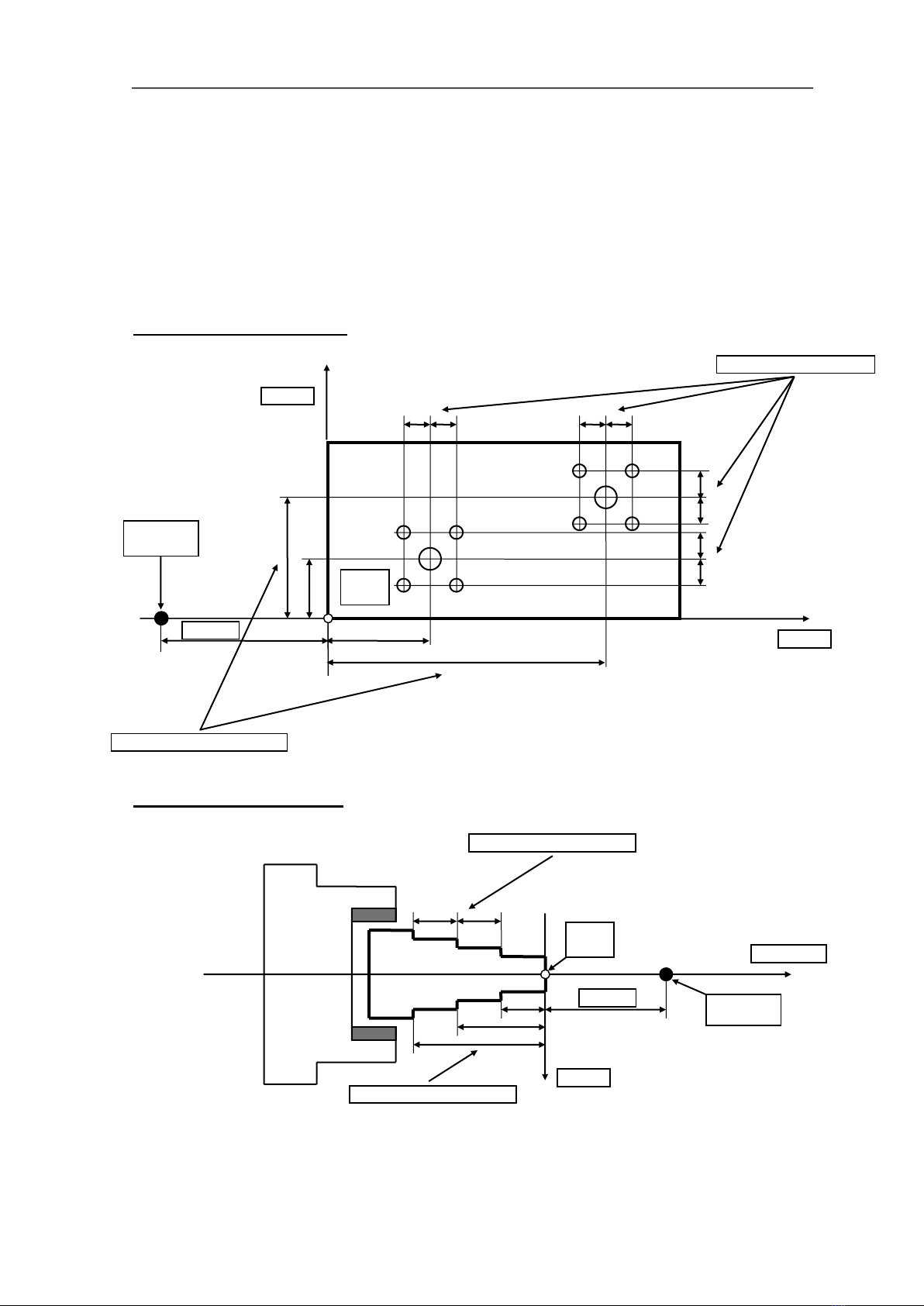
In order to clearly understand the operating procedures described in this manual,
the meanings of the following terms must be absolutely clear.
See the figure below:
SPACE 2000 - M version
SPACE 2000 - T version
PIECE
ZERO
“ABS” ABSOLUTE DIM.
“INCR” RELATIVE DIM.
MACHINE
ZERO
“0” REF
Z+Z1-AXIS
X-AXIS
“INCR” RELATIVE DIM.
“ABS” ABSOLUTE DIM.
MACHINE
ZERO
“0” REF
PIECE
ZERO
X-AXIS
Y-AXIS

SPACE 2000 (T and M versions) OPERATION MANUAL
4
Operation panel
SPACE 2000 T - SPACE 2000 RIF T version
Axis selection key
...... Number keys for dimension setting
Decimal point setting key
Sign setting key
Setting confirmation key
Cancel key
Function enabling key
Tool enabled selection key
Absolute to incremental dimension and vice-versa
switching key
Power supply connected signal
Signalling of “absolute zero” dimension
Signalling of dimension expressed in inches
Signalling of position display
Signalling of diametral dimension (only for X-axis)
X
Z
Z1
0
9
CL
F
TOOL
ABS
INCR
Ent
,
+/-
ABS
INCH
POS
DIA
PWR
t 0
X
ABS
INCR
Z
TOOL
Z1
7
8
9
4
5
6
1
2
3
0
,
+/-
F
CL
Ent
logan
12345.67
X
ABS
INCH
POS
DIA
PWR
12345.67
Z
12345.67
ABS
INCH
POS
Z1
TOOL
ABS
INCH
POS

SPACE 2000 (T and M versions) OPERATION MANUAL
5
SPACE 2000 M - SPACE 2000 RIF M version
Axis selection key
...... Number keys for dimension setting
Decimal point setting key
Sign setting key
Setting confirmation key
Cancel key
Function enabling key
Origin enabled selection key
Absolute to incremental dimension and vice-versa
switching key
Power supply connected signal
Signalling of “absolute zero” dimension
Signalling of dimension expressed in inches
Signalling of position display
X
Y
Z
0
9
CL
F
ORG
ABS
INCR
Ent
,
+/-
ABS
INCH
POS
PWR
o0
X
ABS
INCR
Y
ORG
Z
7
8
9
4
5
6
1
2
3
0
,
+/-
F
CL
Ent
logan
12345.67
X
ABS
INCH
POS
PWR
12345.67
Y
12345.67
ABS
INCH
POS
Z
ORG
ABS
INCH
POS

SPACE 2000 (T and M versions) OPERATION MANUAL
6
SPACE 2000 M 4 axis version
Axis selection key
….. Number keys for dimension setting
Decimal point setting key
Sign setting key
Setting confirmation key
Cancel key
Function enabling key
Absolute to incremental dimension and vice-versa
switching key
Power supply connected signal
Signalling of “absolute zero” dimension
Signalling of dimension expressed in inches
Signalling of position display
X
ABS
INCR
Y
Z
7
8
9
4
5
6
1
2
3
0
,
+/-
F
CL
Ent
logan
12345.67
X
ABS
INCH
POS
PWR
12345.67
Y
12345.67
ABS
INCH
POS
Z
ABS
INCH
POS
12345.67
ABS
INCH
POS
W
W
ABS
INCR
0
9
CL
F
Ent
,
+/-
ABS
INCH
POS
PWR
X
Y
W
Z

SPACE 2000 (T and M versions) OPERATION MANUAL
7
Basic operating functions
This chapter provides detailed descriptions of the procedures to be followed to
enable the SPACE 2000 most elementary functions. For easier learning, this part
of the manual has been divided into "modules", each one of which describes a
single operative procedure. Regardless of its length, each "module" has the same
simple structure.
TITLE OF MODULE
The title is followed by a brief explanation of the function performed by the
procedure that provides immediate knowledge of how it works and the
consequences of its use. Whenever necessary, its relationship with other
procedures described in other modules is explained.
Indications on the appropriateness of the function are provided that make
perfectly clear how, why and when the respective function can be used.
To facilitate learning, the operative functions of the SPACE 2000 are described in
the order in which they will most probably be used. Given that many are
independent, they can be used in any order as required.

SPACE 2000 (T and M versions) OPERATION MANUAL
8
The first division line is followed by the necessary conditions that must exist prior
to starting the procedure.
This part of the description must be given careful attention because in many cases
the successful use of a procedure depends on the manoeuvres performed
previously.
Each procedure is composed of a
series of elementary steps.
For each step, the OPERATION
that the operator must perform on
the machine or the keys that must
be pressed is defined in the first
column.
The CONSEQUENCES and how
the SPACE 2000 responds to the
operator's manoeuvres
(indicated in the first column) are
shown in the second column.
Any particular conditions,
differences or variations from normal
use are described under IF
NECESSARY in the third column,
which explains how to avoid or
remedy error conditions and resume
normal use.
Each elementary step is separated
from the previous step and the
following step by a division line.
Expert operators who have
already acquired working
experience with the SPACE 2000
can skip reading the second
column and concentrate solely
on the first, which provides a
check-list of the operations to be
performed.
Readers of the manual for the first
time are advised to pay special
attention to the warnings and
information written in boldface or
underlined.

SPACE 2000 (T and M versions) OPERATION MANUAL
9
Power supply connection
During this phase, the SPACE 2000 self-diagnostics program runs an internal
operating check and then prepares itself for the following operations to be
performed by the operator if the outcome is positive.
The system must:
•be connected to the power mains.
•have the inputs of the axes connected to the respective position transducers
(encoders or optical scales).
•have its digital parameters programmed adequately to the specifications of the
system in which it will be installed.
Consult the section of the manual entitled "MACHINE PARAMETER
PROGRAMMING” for further details.
Set the power supply switch on the
rear panel in ON position.
The SPACE 2000 PWR LED
begins flashing as the internal
operating check is run.
At the end of the check, the PWR
LED remains lit up steadily and all
the display conditions that were
valid before switching off are re-
proposed with flashing LED. The
flashing of the dimensions means
that these dimensions can be
considered valid, provided that:
• the axes have not been shifted
with the SPACE 2000 power
supply switched off;
• the internal memory has not been
set to zero (the ZERO POWER
RAM offers a minimum duration of
10 years).
All the INCH, ABS, and POS LEDs
are switched off.
Whenever anomalies are present,
the X-axis display will provide a
message that identifies the type of
anomaly (see TROUBLE-
SHOOTING)
If the buffer battery option is not
present and the previously
memorised PIECE ZERO must be
restored, proceed as described for
the PIECE ZERO RESTORATION
function.
Select the key:
The flashing of the dimensions
comes to an end, the LEDs, the
functions and the origin enabled
resume the status they had prior to
the last time the readout was
switched off.
The SPACE 2000 is now ready for
operation.
Ent
Tabla de contenidos
Otros manuales de Cables y conectores de Logan


