LIVEXPERT LiveTally Box Manual de usuario

OperatiOn Manual - (v 2.0)
REMOTE
CONVERTER
AIR
REMOTE
CONVERTER
AIR
Wired and Wireless Tally Transmission sysTem

LiveTaLLy - OperaTiOn ManuaL - page
2
Table of Contents
INTRODUCTION ...........................................................SECTION 1.0
OVERVIEW ..................................................................SECTION 1.1
CONTENT ....................................................................SECTION 1.2
SETTING UP ................................................................SECTION 2.0
WARRANTY ................................................................. SECTION 3.0
GPI AND REMOTE CONNECTIONS ................................ APPENDIX 1
REMOTE
CONVERTER
AIR
REMOTE
CONVERTER
AIR

LiveTaLLy - OperaTiOn ManuaL - page
3
1.0 - Introduction - please read the following notes. They will help
you to get the most from your system.
Note 1: Some of the transmitter settings are stored in battery-backed memory. If the transmitter is not used for a long
time, it is possible that some of these settings may revert to the default condition.
Note 2: If you have any comments or questions about this manual, please write to [email protected].
1.1 - Overview
LiveTally Air is a wireless tally transmission system consisting of a transmitter unit and a number of camera-mounted
battery-powered receiver units. LiveTally Air can work from 4 to 16 GPI ports with any vision mixers and from a USB
connector with TriCaster live production systems.
The receiver units are powered by rechargeable Nickel-metal hydride cells. These are charged via a breakout lead from
the transmitter unit. The battery life is typically 40-50 hours of continuous operation.
1.2 - Package content
Your LiveTally Air package should contain:
• 1x LiveTally Air Transmitter
• 1x Power Supply
• 1x Power Cord
• 1x stub aerial
• 1x USB cable for TriCaster connection
• Some LiveTally Air or LiveTally Remote Receivers depending on the number you ordered
• 1x stub aerial per LiveTally Air you ordered
• 1x RJ45 Male to Male RJ-45 Cat5 cable per LiveTally Air you ordered
• 1x 1/4’’ Screws Adapter Kit for Camera Flash Hot Shoe Mount per LiveTally receiver (Air or Remote)
• 1x 1/4» Male to 1/4» Male Threaded Screw Adapter per LiveTally receiver (Air or Remote)
If there is any item missing, please contact your dealer.

LiveTaLLy - OperaTiOn ManuaL - page
4
2.0 - Setting Up
2.1 - The Transmitter
Connect the GPI output from the vision mixer/switcher with a GPI cable and connect the other end to the connector on
the back of the transmitter unit marked “PROGRAM”.
If your vision mixer handles Preview Tally, connect a second GPI cable between the second GPI output from the vision
mixer and to the connector on the back of the transmitter unit marked “PREVIEW”
In order to build the suitable GPI cable for your vision mixer, please refer to the wiring details from Appendix 1.
If you are using a TriCaster HD model, connect the USB connector to any USB port of the Tricaster using the provided
cable.
Download the software driver for TriCaster from : http://www.3dstorm.com/fr/support2/download
Copy the software to your TriCaster drive. Run the installation by clicking twice on the file name. Follow the instruction.
After installation, the software will start automatically each time the Tricaster is powered on. There is no settings or
parameters. Connection to the Livetally system will be automatic.
to the GPI output of the vision mixer
to the GPI Preview output of the vision mixer To the USB port of Tricaster
Power Supply
To wired LiveTally Receivers
and to recharge LiveTally Air Receiver

LiveTaLLy - OperaTiOn ManuaL - page
5
Operation of the mixer program and preview buses will cause the receiver tally lights to operate. You will see a range
of a maximum of 1.3 mile / 2 km outdoors depending on terrain. The system uses coded channels in the license-free
866MHz band, so interference with or from other equipment is unlikely.
Attach a stub aerial to the BNC connector located at the rear of the LiveTally Air Transmitter.
Apply power to the unit. The following message will be displayed depending on the transmitter model:
LiveTally Transmitter TX4 : support for up to 4 cameras
LiveTally Transmitter TX8 : support for up to 8 cameras
LiveTALLY Transmitter TX16 : support for up to 16 cameras
The following sections on operation refer to the transmitter display as it appears in the image above. “Src” refers to the
current status of each receiver. The “-“ mean that these sources are not activated. Depending on the factory preset of
each transmitter, there could be any combination of “N” or “-“ when powering on a transmitter at the first time.
2.1.1 - Step 1: Configuring the sources
By pressing once on the MENU button, you will enter the menu to activate or de-activate each source corresponding to
each receiver.
LiveXpert base4
Src1>4: ----
LiveXpert base8
Src1>8: --------
LiveXpert base16
Src1>8: --------
Source 1
Enable? Y

LiveTaLLy - OperaTiOn ManuaL - page
6
We recommend that each source number matches with the number of the camera on which you will install the
receiver. Ex: Source 1 = Receiver 1 = Camera 1.
To configure Source 1, keep pressing on SHIFT button and press the SCROLL+ button to switch between “Y” : activated,
“N” : de-activated and “W” : wired connection to receiver.
To configure the next source, release the SHIFT button and press once on SCROLL+. The screen displays then :
To change the status, keep pressing on SHIFT button and press the SCROLL+ button as you did for Source 1. Repeat
the process for each source. If you want to review one previous source, you can press SCROLL- to select the source
you want to check.
If you are not going to use all the sources, we recommend that you de-activate the unused sources as this reduces the
polling time of the transmitter.
2.1.2 - Step 2 : Channel Selection
Press twice on the MENU button to enter the “Channel Select” menu.
LiveTally Air can use any one of 4 channels within the 866MHz band. This menu allows you to choose between 4
different channel frequencies for the RF transmission between transmitter and receivers. This feature is useful when
two LiveTally Air systems are being used in the same area. This configuration has to be done from the transmitter only,
the receivers will be updated automatically.
To change a channel, keep pressing the SHIFT button and press SCROLL+ one or more times to reach the value you
want from 1 to 4.
2.1.3 - Step 3 : Remote Handshake status
The system incorporates a handshake function, the default condition for which is disabled. If enabled, the transmitter
periodically polls the enabled receiver channels. If contact is lost with one or more receivers, the LED screen will
display 2 blinking LED at the beginning and at end of the first line of the screen.
Source 2
Enable? Y
Channel Select
(1..4) 4

LiveTaLLy - OperaTiOn ManuaL - page
7
To activate this option, press on the MENU button to display this screen.
Keep pressing SHIFT button and press SCROLL+ to change “Off” to “On”. The LED’s will start blinking immediately if
one or more receivers is out of contact.
2.1.4 Step 4 : Setting the GPI input sense
Press on the MENU button until this menu appears.
When using few vision mixers, the GPI input sense may need to be inverted. Keep this parameter to NORMAL unless the
Tally systems would not work properly.
To change this parameter from this menu location, keep pressing SHIFT then SCROLL+ button to swap to “INVERTED”.
Press MENU button once to exit from the configuration menu.
2.1.5 Step 5 : PGM/PVW Reverse
Press on the MENU button until this menu appears.
Remote Handshake
<Off>
Remote Handshake
<ON>
GPI Input Sense
<NORMAL>
PGM/PVW Reverse
Rem1>4 NNNN
LiveTaLLy - OperaTiOn ManuaL - page
8
This setting allows to reverse Program and Preview color. A receiver will turn Green instead of Red when the
corresponding camera will be set to PGM row of the vision mixer, and it will turn Red instead of Green when the camera
will be set to Preview row.
Press on SCROLL+ to choose the receiver to be reversed, then hold SHIFT and press SCROLL+ to change N to R. N
stands for Normal and R for Reverse.
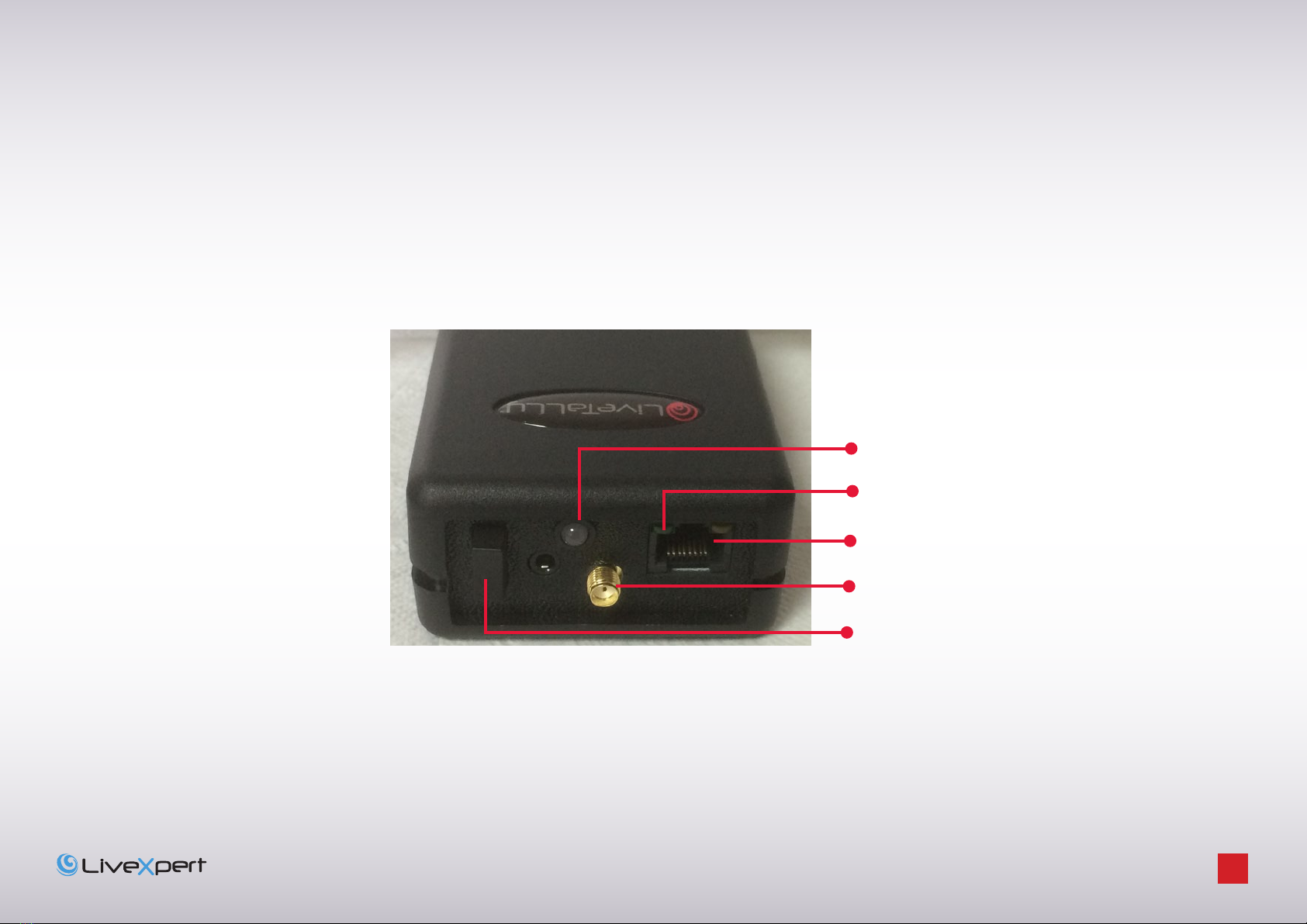
2.2 - Configuring the wireless Receivers
Rear panel of LiveTally Air receiver
Connector for charging the receiver and
connecting the LED Extender
Connector for the aerial
3 positions Power switch
Cameraman LED status
Power status

LiveTaLLy - OperaTiOn ManuaL - page
9
Attach a stub aerial to each of the receiver aerial connectors.
The Power switch has 3 positions: set to middle the receiver is powered OFF, press the switch to Top to switch on both
the front panel and the rear LED of the receiver. Press the switch to bottom to switch on the rear LED only. In each case,
the front and rear panel LEDs flash for a few seconds and a green light closed to the RJ45 connector on the rear panel
indicates power on.
If there is no power to the receiver, charge the unit and retry.
2.2.1 - Charging
Recharge the receivers via the LiveTally transmitter. Connect one or more receivers to the RJ45 connectors at the back
of the transmitter, after a few seconds, the small yellow led on the rear of the receiver will light up. Normal charging
time is about 6 hours, and the led will go out when the charging is complete. Please note that the transmitter has to be
powered on in order to charge the receivers. It is not necessary to connect it to the vision mixer.
2.2.2 - Configuration
Switch OFF all receivers and power ON the Transmitter.
Press 6 times the MENU button to display this menu.
Hold down SHIFT and press SCROLL+
Press SCROLL- button to enter the configuration of the Receivers
Config System
<Shft> <+> = GO
Identify Rx <+>
Config Rx <->
Multiscan <+>
Single scan <->

LiveTaLLy - OperaTiOn ManuaL - page
10
Two modes are available if you need to configure all Receivers (Multiscan) or if you need just to add one receiver to an
existing configuration.
2.2.2.1 Multiscan mode
Press SCROLL+ button to enter the Multiscan mode
This mode allows configuring several receivers one after the other. It is necessary to enter here the first ID for the serie
of receiver. If the first receiver to be configured matches with Camera 1, then just keep 01. If you need to configure
receivers for camera 2 to 5 for example you should set the first value to 02 by holding SHIFT button and pressing
SCROLL+
Press SCROLL+ to validate.
Enter here the ID for the last Receiver of the serie you want to configure. In the above example you should set 05 by
pressing 4 times on SHIFT and SCROLL+ buttons.
Press SCROLL+ to validate.
The transmitter will ask to Power on the first receiver that will be configured for the first camera. All other receivers
have to remain switched off.
Power On the receiver and wait until it completed to blink. Then press SCROLL+ button on the transmitter. The
transmitter will process the automatic scan and configuration of the receiver. When completed, it will prompt to
configure the second receiver.
Then the first receiver has to be switched off and you can power on the second receiver. Then press SCROLL+ button
on the transmitter.
Repeat this process until all receivers will be configured.
Configure Rx (M) Set
1st ID [01]
Configure Rx (M) Set
Last ID [01]
CfgRx: Power on
First Rx ONLY
CfgRx: Power on
Next Rx ONLY
Otros manuales para LiveTally Box
1
Tabla de contenidos
Manuales populares de Sistema de micrófono de otras marcas


Sennheiser
Sennheiser Evolution Wireless Digital EW-DX EM 2 Manual de usuario

Alpha Technologies
Alpha Technologies RBMS Manual de usuario

SWIT Electronics Co.,LTD.
SWIT Electronics Co.,LTD. CW-S150 Manual de usuario

Shure
Shure UA844 Manual de usuario

Panasonic
Panasonic SHFX70 - DVD HOME THEATER WIRELESS SYSTEM Manual de usuario

Pyle
Pyle PDWM5000 Manual de usuario