LIVARNO LUX 273024 Especificaciones técnicas

LED SOLAR WALL LIGHT
IAN 273024
LED SOLAR WALL LIGHT
Assembly, operating and safety instructions
APPLIQUE MURALE SOLAIRE À LED
Instructions de montage, d‘utilisation et
consignes de sécurité
LED-SOLAR-WANDLEUCHTE
Montage-, Bedienungs- und Sicherheitshinweise
LED-SOLAR-WANDLAMP
Montage-, bedienings- en veiligheidsinstructies

GB/IE Assembly, operating and safety instructions Page 5
FR/BE Instructions de montage, d‘utilisation et consignes de sécurité Page 14
NL/BE Montage-, bedienings- en veiligheidsinstructies Pagina 24
DE/AT / CH Montage-, Bedienungs- und Sicherheitshinweise Seite 34
A B C
H I
D E F
HG00375A
1 2 3
12 7
6
8
9
G
11
13
10

A B C
G H I
D E F
HG00375B
1 2 3 4
57
6
8
11
10
9

A B C
G H I
D E F
HG00375C
1 2 3 4
5
6
8
7
10
9
11

5GB/IE
Intended use......................................................................................................................Page 6
Parts description ............................................................................................................Page 6
Technical Data..................................................................................................................Page 6
Scope of delivery...........................................................................................................Page 6
General safety instructions...................................................................................Page 7
Safety instructions for rechargeable batteries........................................................................Page 8
Function..................................................................................................................................Page 8
Installation..........................................................................................................................Page 9
Replacing the rechargeable batteries.....................................................................................Page 10
Winter-time use.........................................................................................................................Page 10
Cleaning and Care........................................................................................................Page 11
Troubleshooting .............................................................................................................Page 11
Disposal.................................................................................................................................Page 12
Warranty..............................................................................................................................Page 13

6 GB/IE
LED Solar wall light
Intended use
The LED solar-powered wall light is intended to
illuminate outdoor areas without electrical con-
nection, e.g. garden sheds etc. The LED solar-p
ow-
ered wall light is not suitable for commercial use.
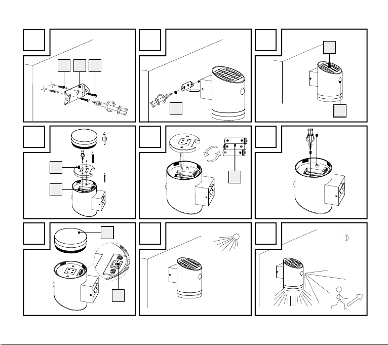
Parts description
1Rawlplug
2Mounting plate
3Screws (4 x 30mm)
4Hanger (for HG00375B/ HG00375C only)
5Receiver (for HG00375B/ HG00375C only)
6Solar cell
7Sensor
8Battery cover
9Battery compartment
10 Rechargeable batteries
11 ON/ OFF switch
12 Screws (3.7 x 5.5 mm) (for HG00375A only)
13 Lamp Shade (for HG00375A only)
Technical Data
Operating voltage: 3.6V
Rechargeable
batteries:
3 x 1.2V NiMH batteries
,
900mAh, AAA
Light bulb: 4 LEDs, approx. 0.5 W
(LEDs not replaceable.)
Solar cell: approx. 5.5 V, approx.
100mA
Sensor: Range: max. 5m, detection
angle: approx. 100° hori-
zontal, approx. 90° vertical
Protection class: IP43 (spray-proof)
Scope of delivery
Check immediately after unpacking that the
parts are complete and that the product is in
proper condition.

7GB/IE
1 Main unit
3 NiMH-rechargeable batteries type AAA,
1.2V , 900 mAh – (preinstalled)
1 Mounting plate
2 Screws (4 x 30mm) (Model HG00375A)
2 Rawlplugs ø 6mm (Model HG00375A)
2 Screws (3.7 x 5.5mm) (Model HG00375A)
3 Screws (4 x 30mm) (Model HG00375B/
Model HG00375C)
3 Rawlplugs ø 6mm (Model HG00375B/
Model HG00375C)
1 Instructions for assembly and use
General safety
instructions
BEFORE USING THE PRODUCT, PLEASE
FAMILIARISE YOURSELF WITH ALL OF THE
SAFETY INFORMATION AND INSTRUCTIONS
FOR USE! WHEN PASSING THIS PRODUCT
ON TO OTHERS, PLEASE ALSO INCLUDE ALL
THE DOCUMENTS!
This device may be used by children age
8 years and up, as well as by persons with
reduced physical, sensory or mental capaci-
ties, or lacking experience and/or knowle
dge,
so long as they are supervised or instructed
in the safe use of the device and understand
the associated risks. Children should not be
allowed to play with the device. Cleaning
and user maintenance should not be per-
formed by children without supervision.
Never leave children unsupervised with the
packaging material. The packaging material
represents a danger of suffocation. Children
frequently underestimate the dangers.
Keep children out of the area you are work-
ing in. A large number of screws and other
small parts are included with delivery. These
may prove life-threatening if swallowed or in-
haled.
Do not use this product if you notice any
damage!
8 GB/IE
Safety instructions for
rechargeable batteries
DANGER TO LIFE!
Rechargeable batteries are not intended to be in
the hands of children. If accidentally swallowed
seek immediate medical attention!
CAUTION! EXPLOSION
HAZARD!
Never throw batteries into fire or water!
Do not exert mechanical strain on batteries!
Do not use disposable batteries.
Never short-circuit or open rechargeable
batteries.
Risk of equipment damage
Only use the battery type specified!
When inserting the battery ensure the correct
polarity! This is shown inside the battery
compartment!
If necessary, clean the battery and device
contacts before inserting the battery!
Function
Solar cell
The solar cell 6converts energy from sunlight
into electricity. Using this electricity, the installed
batteries 10 are charged in the battery com-
partment 9.
These batteries store the electricity fed by the
solar cell. Fully charged batteries deliver light
for approximately 6 hours, when the ON/OFF
switch 11 is in the „ON“ position.
I
n summer, completely drained batteries take ab
out
1 to 2 days to fully recharge in good sunlight.
Sensor
During periods of twilight or darkness, the sen-
sor 7registers a change in the angle of heat
radiation, triggered by people passing by the
sensor (Fig. I). When the sensor recognises a
moving person the light is switched on. The light
goes off after approx. 1 minute, after the last
movement was recognised.

9GB/IE
Installation
When selecting the mounting location, pay
attention to the following:
1.
The solar cell
6
requires direct sunlight wh
en
possible. Ideally, the solar cell surface will be
directed to the south. The horizontal direction
of the solar cell is dependent on mounting
on a vertical wall.
2. Depending on the mounting height (ideally
at 2m) the sensor 7has a detection range
of max. 5m with a detection angle of 100°
horizontally and 90° vertically.
3. Be sure the sensor is not illuminated by street
lighting at night. This can influence the effect.
For model HG00375A: Fix the mounting
plate 2using the provided rawlplugs 1
(ø 6 mm) and the provided screws 3
(Fig. A).
For model HG00375B/HG00375C:
Fix the mounting plate 2using the provided
rawlplugs 1(ø 6 mm) and the provided
screws 3. Ensure that the arrow on the
marking of the mounting plate ( UP) is show-
ing vertically upward (Fig. A).
Note: The enclosed mounting material is
suitable for ordinary masonry construction.
Other wall substrates may require other fas-
tening materials. Seek specialist advice when
in doubt.
Set the ON /OFF switch 11 to the position
„ON“ to start the operation of the light (For
HG00375A, the ON/OFF switch is inside
the lamp shade 13 at the base. Open the
lamp shade to set the switch.) (Fig. G).
Note: In the „OFF“ position both the light
and the charging function are disabled.
For model HG00375A: Fix the light
onto the mounting plate using the provided
screws 12 (Fig. B).
For model HG00375B/HG00375C:
Attach the device to the mounting plate in
such a way that the hangers 4of the
mounting plate grip in the receivers 5on
the back of the device. Slide the device
downwards until the hangers click into
place in the receivers (Fig. B).
Tabla de contenidos
Idiomas:
Otros manuales de Linterna de LIVARNO LUX

LIVARNO LUX
LIVARNO LUX 273745 Especificaciones técnicas

LIVARNO LUX
LIVARNO LUX 43174 Manual de usuario

LIVARNO LUX
LIVARNO LUX 284725 Manual de usuario

LIVARNO LUX
LIVARNO LUX 106339 Especificaciones técnicas

LIVARNO LUX
LIVARNO LUX Z31906 Especificaciones técnicas

LIVARNO LUX
LIVARNO LUX 284725 Manual de usuario

LIVARNO LUX
LIVARNO LUX 295794 Especificaciones técnicas

LIVARNO LUX
LIVARNO LUX HG03508B Especificaciones técnicas

LIVARNO LUX
LIVARNO LUX 10603A Especificaciones técnicas

LIVARNO LUX
LIVARNO LUX 276249 Manual de usuario


