Le Cappe WALL MOUNT HOODS Manual de usuario
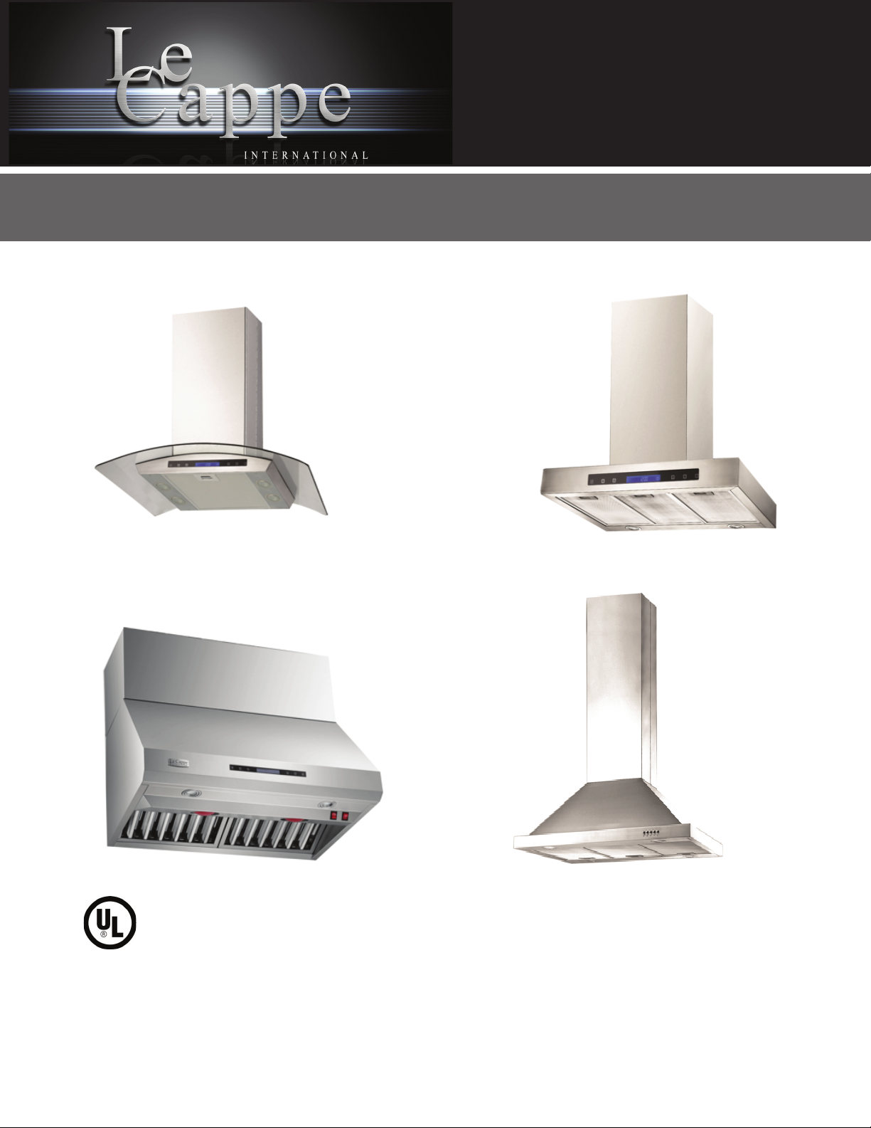
INSTRUCTIONS GUIDE AND USER MANUAL WALL MOUNT HOODS.
IMPORTANT:
Read and save these instructions.
NOTICE:
Installer: Leave this guide with the homeowner
Homeowner: Keep this guide for future reference

• The installation in this manual is intended for qualified installers, service technicians or persons with similar
qualified background. Installation and electrical wiring must be done by qualified professionals and in accor-
dance with all applicable codes and standards, including fire-rated construction.
• DO NOT attempt to install this appliance yourself. Injury could result from installing the unit due to lack of
appropriate electrical and technical background.
• Range hood may have very sharp edges; please wear protective gloves if it is necessary to remove any parts
for installing, cleaning or servicing.
• Activating any switch ON before completing installation may cause ignition or an explosion.
• Due to the size and weight of this range hood, two people installation is recommended.
To reduce the risk of fire, electric shock, or injury to persons:
• For general ventilating use only. DO NOT use to exhaust hazardous or explosive materials and
vapors.
• The combustion air flow needed for safe operation of fuel-burning equipment may be affected by this unit’s
operation. Follow the heating equipment manufacturer’s guideline and safety standards such as those pub-
lished by the National Fire Protection Association (NFPA), and the American Society of Heating, Refrigeration
and Air Conditioning Engineers (ASHRAE), and the local code authorities.
• Before servicing or cleaning unit, switch power OFF at service panel and lock service panel to prevent power
from being switched ON accidentally.
• Clean grease laden surfaces frequently. To reduce the risk of fire and to disperse air properly, make sure to
vent air outside. DO NOT vent exhaust into spaces between walls, crawl spaces, ceiling, attics or garages.
• Ducted fans MUST always be vented to the outdoors.
• Use only metal ductwork and this unit MUST be grounded.
• Sufficient air is needed for proper combustion and exhausting of gases through the duct to prevent back draft-
ing.
• When cutting or drilling into wall or ceiling, be careful not to damage electrical wiring or other hid- den utilities.
• All electrical wiring must be properly installed, insulated and grounded.
• Old duct work should be cleaned or replaced if necessary to avoid the possibility of a grease fire.
• Check all joints on duct work to insure proper connection and all joints should be properly taped.
• Use this unit only in the manner intended by the manufacturer. If you have questions, contact the
vendor.
To reduce the risk of a stove top grease fire:
• Keep all fan, baffle, spaces, filter, grease tunnel, oil container and grease-laden surfaces clean. Grease
should not be allowed to accumulate on fan, baffle, spaces, filter, grease tunnel and oil container.
• Always turn range hood ON when cooking at high heat or when cooking flaming foods.
• Use high settings on cooking range only when necessary.
• Never leave surface units unattended at high settings. Boil over cause smoking and greasy spillovers
that may ignite. Heat oils slowly on low or medium settings.
• Clean ventilating fan frequently.
• Always use appropriate cookware and utensils size.
• Always use cookware appropriate for the size of the surface element.
Important Safety Notice
Read all Instructions before Installing and operating this appliance
1
To reduce the risk of injury to persons in the event of a stove top grease fire:
• SMOTHER FLAMES with a close-fitting lid, cookie sheet, or metal tray, then turn OFF the burner.
BE CAREFUL TO PREVENT BURNS. NEVER PICK UP A FLAMING PAN—you may be burned. KEEP FLAM-
MABLE OR COMBUSTIBLE MATERIAL AWAY FROM FLAMES. If the flames DO
NOT go out immediately, EVACUATE AND CALL THE FIRE DEPARTMENT or dial your local emergency
service immediately.
• DO NOT USE WATER, including wet dishcloths or towels — a violent steam explosion will result.
Use an extinguisher ONLY if:
You know you have a Class A, B, C extinguisher, and you already know how to operate it.
The fire is small and contained in the area where it is started.
The fire department is being called.
You can fight the fire with your back to an exit.
To reduce the risk of injury to persons in the event of a gas leaks:
• Extinguish any open flame.
• DO NOT turn on the range hood fan or any type of ventilator.
• DO NOT turn on the lights or any type of appliance.
• Open all doors and windows to disperse the gas. If you still smell gas, call the gas company and fire depart-
ment, or dial your local emergency service immediately.
Your safety and the safety of others is very important. We have provided many important safety mes- sages in
this manual and on your appliance. Always read and obey all safety messages. All safety mes- sages will tell
you what the potential hazard is, tell you how to reduce the chance of injury, and tell you what can happen if the
instructions are not followed.
This is the safety alert symbol. This symbol alerts you to potential hazards that can hurt you and others. All
safety messages will follow the safety alert symbol and the word “WARNING”.
The manufacturer and/or distributor/reseller declines all responsibility in the event of failure to ob-
serve the instructions given here for installation, maintenance and suitable use of the product.
The manufacturer and/or distributor/reseller further declines all responsibility for injury due to
negligence and the warranty of the unit automatically expires due to improper maintenance.
The manufacturer and/or distributor/reseller will not be held responsible for any damages to per- sonal
property or real estate or any bodily injuries whether caused directly or indirectly by the range
hood.
Important Safety Notice
Read all Instructions before Installing and operating this appliance
WARNING
2
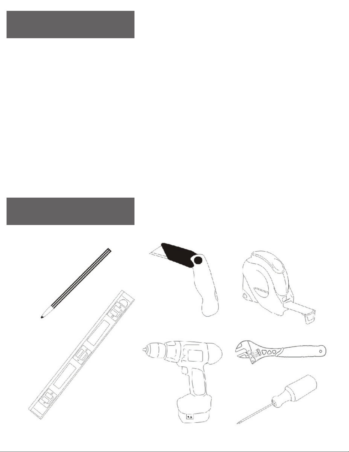
Table of Content
Tools Needed:
INSTALLATION
Tools needed. 3
Parts supplied. 4
Venting requirements. 5
Mount heights & clearance. 5-6
Venting methods & Re-calculating functions 7
Charcoal Filter Installation 8
Electrical Requierements 8
Preparations 9
Installation 10
USE AND CARE
Range hood operations 11-12-13
Troubleshooting. 14
Use and care information. 15
Specications 15-16
MAINTENANCE
Cleaning, replacing lter & light bulb 17
WARRANTY
Warranty, Coverage & exceptions. 18
3
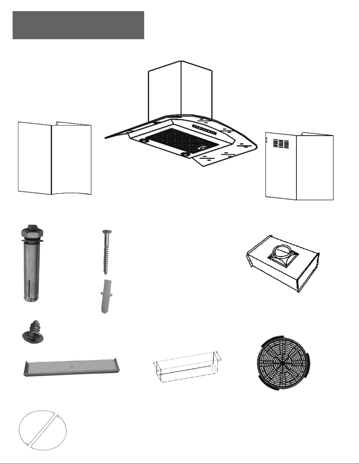
Parts supplied:
Range Hood (Vary By Model)
Lower Standard Chimney
Main Unit
Upper Standard Chimney
A
Qty: 2PCS
D
Qty: 4PCS
B
Qty: 1PCS
C
Qty: 1PCS Air Diverter
(Optional re-circulating kit, pre-installed
when ordered together with range hood)
Charcoal filter
(Optional re-circulating kit, pre-installed
when ordered together with range hood)
Support frame extension
(Length varies with ceiling heigh Grease/Oil Cup
Flappers Qty: 2PCS
4
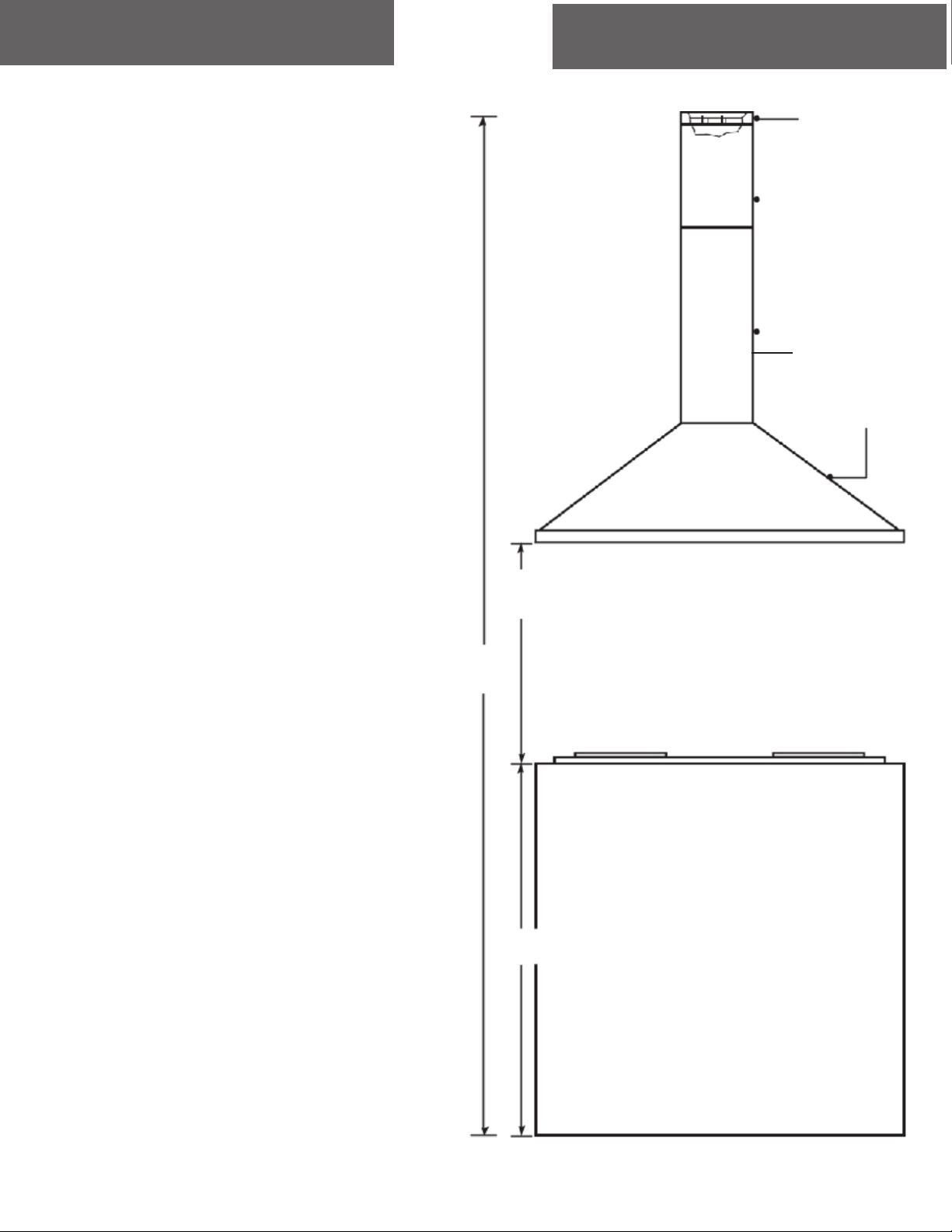
Venting Requirements Height & Clearance
• Vent system must terminate to the outside (roof
or side wall).
• DO NOT terminate the vent system in an at- tic
or other enclosed area.
• DO NOT use 4” (10.2 cm) laundry-type wall
caps.
• Use metal /aluminum vent only. Rigid metal
(Not Included).
aluminum vent is recommended.
• DO NOT use plastic vent.
•Always keep the duct clean to ensure proper
airflow.
• Calculate the following figures before
installation:
1.Distance from the floor to the ceiling.
2.Distance between the floor to the coun-
tertop/stove (Usually 36 Inches).
3.Distance between the countertop/stove to the
range hood.
We recommend (25.5’ to 27 1/2’ Inches).
4. Height of hood and duct cover.
For the most efficient & quiet operation:
• It is recommended that the range hood be
vented vertically through the roof through 6”
(15.24 cm) or bigger round metal / aluminum
vent work.
• The size of the vent should be uniform.
• Use no more than two 90° elbows.
• Make sure there is a minimum of 24” (61 cm)
of straight vent between the elbows if more than
one elbow is used.
• DO NOT install two elbows together.
The length of vent system and number of
elbows should be kept to a minimum to pro- vide
efficient performance.
• The vent system must have a damper. If roof
or wall cap has a damper, DO NOT use damper
(if supplied) on top of the range hood.
• Use silver tape or duct tape to seal all joints in
the vent system.
• Use caulking to seal exterior wall or roof open-
ing around the cap.
Maximum* ceiling clear-
ance 106” at 27.5” hood
mounting height above
countertop/stove (may vary
with different model).
Chimney extensions
available for higher ceiling.
Support Structure
Support
Structure
Standard
Upper
Chimney
Extension available*
Standard
Lower
Chimney
Extension available*
Min: 25.5”
Max: 27.5”
Max*: 101”
36” base
Range hood
5
Important
• A minimum of 6” round (standard for this range hood) or 3-1/4 x 10” rectangular duct (purchased sepa-
rately) must be used to maintain maximum airflow efficiency.
• Flexible 6” round duct, always use rigid type metal/aluminum ducts if available to maximize airflow
when connecting to provided duct.
• Please use Duct Run Calculation below to compute the total available duct run when using elbows,
transitions and caps.
• ALWAYS, when possible, reduce the number or transitions and turns. If long duct run is required,
increase duct size from 6” to 7” or 8”. If a reducer is used, install a long reducer instead of a pancake
reducer.
• Reducing duct size will restrict airflow and decrease airflow, thus reduce duct size as far away from
opening as possible.
• If turns or transitions are required: Install as far away from opening and as far apart, between 2, as pos-
sible.
• Minimum mount height between stove top to hood bottom should be no less than
28-inch*.
• Maximum mount height between stove top to hood bottom should be no higher than 31-inch*.
• It is important to install the hood at the proper mounting height. Hoods mounted too low could result in
heat damage and fire hazard; while hoods mounted too high will be hard to reach and will loose its
performance and efficiency.
• If available, also refer to stove top manufacturer’s height clearance requirements and recommended
hood mounting height above range.
* Due to different ceiling height configurations, recommended height may not be applicable.
Minimum Duct Size:
• Round - 6” minimum
• Rectangular - 3-1/4 x 10” minimum (requires a 6” to 3-1/4x10” adaptor, not supplied)
To calculate the length of the system you need, deduct the equivalent feet for each vent piece used in
the system from the recommended maximum duct run.
Duct Run Calculation example:
One roof cap, one 90º elbow, and one 45º elbow
used: 9ft + 5ft = 14 ft used.
Deduct 14 ft from 30ft, 16ft maximum available for
straight duct run. If no elbows are used, maximum
run is 30 ft (recommended).
Recommended maximum run
R6” or 3-1/4 x 10” duct
Vent piece deduction
Each 90º elbow used
Each 45º elbow used
Each 6” to 3/14 x 10” transition used
Side wall cap with damper
Roof cap
9 ft
5 ft
7 ft
0 ft
0 ft
30 ft
Duct Run Calculation:
6
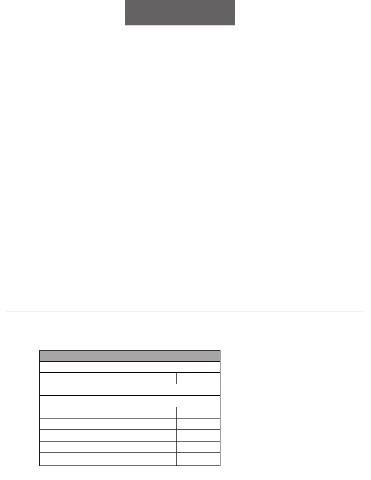
Venting Methods:
Re-Circulating Function Methods:
This range hood is factory set for venting through the roof or wall.
• Vent work can terminate either through the roof or wall. To vent through a wall, a 90°
elbow is needed.
IMPORTANT:
• NEVER exhaust air or terminate duct work into spaces between walls, crawl spaces,
ceiling, attics or garages. All exhaust must be ducted to the outside.
• Use metal/aluminum duct work only.
• Fasten all connections with sheet metal screws and tape all joints with certified Silver
Tape or Duct Tape.
• Use caulking to seal exterior wall or roof opening around the cap. ( Not included)
Re-circulating function is intended for applications where an exhaust duct work is not possible to be
installed. When converted, the hood functions as a purifying hood rather than an exhaust hood. Fumes
and exhaust from cooking is drawn and filtered by a set of charcoal filters. The air is then purified and
re-circulated back within the home.
• We recommend to ALWAYS exhaust air outside of the home by employing existing or installing new
duct work, if possible. Only when the exhaust option is not possible should you recourse to converting
the hood into a purifying unit.
• When converted to be a “purifying” unit, a charcoal filter is required in addition to its standard aluminum
filter set. Available online only!!!. The standard aluminum filters are intended to capture residue from
cooking, the optional charcoal filters help to purify fumes exhausted from cooking.
Option 1: Vertical roof
venting
Option 2: Horizontal wall venting
Roof cap
Side wall cap
7

Charcoal Filter Installation
Electrical Requirements
NOTE: The charcoal filter or filters are required when using the LeCappe hood as a purifying unit
only if you purchased the range hood with re-circulating kit from us.
1. Remove aluminum filters on hood.
2. Position the charcoal filter or filters depending on model, onto each side of the motor and turn
until it locks. Re-install aluminum filters.
3. Charcoal filters must be replaced after 120 hours of use (or approximately every 2 to 3 months
based on the average of 1 to 2 hours of daily cooking time). Available online only at
www.lecappe.com
It is the customer’s responsibility:
• To contact a qualified electrical installer.
• To assure that the electrical installation is adequate and in conformance with National Electrical Code, ANSI/
NFPA 70 — latest edition*, or CSA Standards C22. 1-94, Canadian Electrical Code, Part 1 and C22. 2 No.
0-M91 - latest edition** and all local codes and ordinances.
If codes permit and a separate ground wire is used, it is recommended that a qualified electrician determine that
the ground path is adequate.
A 120-Volt, 60 Hz, AC-only (USA & Canada standard), fused electrical supply is required on a separate 15-amp
circuit, fused on both sides of the line.
DO NOT ground to a gas pipe.
Check with a qualified electrician if you are not sure that the range hood is properly grounded.
DO NOT have a fuse in the neutral or ground circuit.
IMPORTANT: Save this Installation Guide for electrical inspector’s use. The range hood must be connected
with appropriate wire/plug only.The range hood should be connected directly to the fused disconnect (or circuit
breaker) box through flexible armored or non-metallic sheathed copper cable. A U.L. - or C.S.A. - listed strain
relief must be provided at each end of the power supply cable.
Wire sizes must conform to the requirements of the National Electrical Code ANSI/NFPA 70 — latest edition*,
or CSA Standards C22.1-94, Canadian Electrical Code Part 1 and C22. 2 No. 0-M91 - latest edition** and all
local codes and ordinances. A U.L. - or C.S.A. - listed conduit connector must be provided at each end of the
power supply cable (at the range hood and at the junction box).
Copies of the standards listed may be obtained
from:
National Fire Protection Association Battery-
march Park Quincy, Massachusetts 02269
** CSA International
8501 East Pleasant Valley Road Cleve-
land, Ohio 44131-5575
8
Preparations
NOTE: To avoid damage to your hood, prevent debris from entering the vent opening.
1. Carefully remove the white plastic protective coat from the chimney covers and range hood
2. Determine and mark the center line on the ceiling where the range hood will be installed. Make sure
there is proper clearance within the ceiling or wall for exhaust vent.
3. Due to the weight and size of this unit, please make sure that the support system or framework
being used is stable and secure in the wall.
4. Put a thick, protective covering over counter top, cook top or range to protect from damage or dirt.
Remove any hazardous objects around the area when installing.
5. Mark the locations of the support mounting bracket holes, vent cutout (if used) and power supply
cable cutout on the ceiling. Use drill and saber saw or keyhole saw to cut openings for power supply
cable and vent (see Venting requirements and Electrical requirements.
6. If venting to the outside installs vent system (see Venting Methods). Use caulking to seal exterior
wall or roof openings.
7. Disconnect main electrical supply, prepare and run electrical wiring through ceiling or wall.
8. Leave approximately 12” of electrical cord hanging from the ceiling. Do not restore power until
wiring is completed.
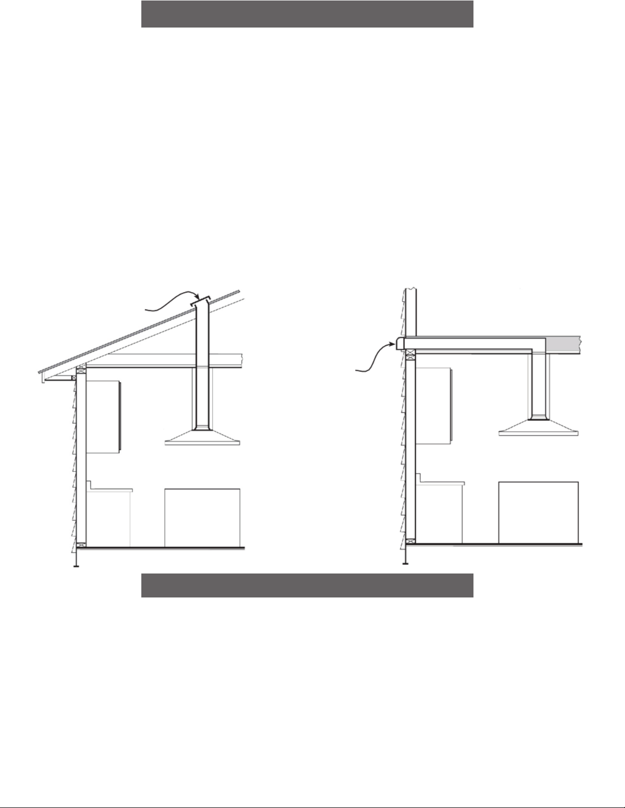
9. Disconnect power cord, remove the aluminum filter by pressing on the latch gently pull the alumi-
num filter toward the direction of dashed arrow as shown in Figure 1.
10. Remove the grease cup by sliding it sideway , see Figure 2 for location of the grease cup.
11. Set aside the aluminum filters and grease cup until the range hood is properly installed.
WARNING
Severe Injury Rotating fan
can cause severe injury.
Stay clear of fan when
motor is running.
9
Tabla de contenidos
Otros manuales de Campana de ventilación de Le Cappe


