
Kyoritsu Electrical Instruments Works, Ltd. KEW 8602 Manual de usuario
Instruction manual
EVSE ADAPTER
KEW 8602

—
1
—
Contents
1. Unpacking......................................................................................... 2
2. Safety precautions............................................................................ 2
3. Features ........................................................................................... 5
4. Instrument layout.............................................................................. 7
5. Test procedures ................................................................................ 8
5.1 Connection ............................................................................... 8
5.2 Pre-Test .................................................................................... 8
5.3 CP (Control Pilot) state check .................................................. 9
5.4 PP (Proximity Pilot) state check ............................................. 11
5.5 CP (Control Pilot) signal error simulation ............................... 11
5.6 PE (Earth fault) error simulation ............................................. 12
5.7 Various tests with measuring instrument (MFT) ..................... 12
5.8 CP (Control Pilot) signal output check.................................... 19
6. Fuse replacement........................................................................... 20
7. Specifications ................................................................................. 21

—
2
—
1. Unpacking
Thank you for purchasing our EVSE adapter KEW 8602.
The following table is a list of the items included with the instrument.
1 Instrument KEW 8602 x1
2 Carrying case MODEL 9202 x1
3 Instruction manual x1
2. Safety precautions
This instrument has been designed, manufactured, and tested
according to IEC 61010: Safety requirements for electrical equipment
for measurement and delivered in the best condition after passing
quality control tests.
This instruction manual contains warnings and safety rules which must
be observed by the user to ensure safe operation of the instrument
and to maintain it in safe condition. Therefore, read through these
operating instructions before starting to use the instrument.
#DANGER
● Read through and understand instructions contained in this
manual before starting to use the instrument.
● Keep the manual at hand to enable quick reference whenever
necessary.
● The instrument is to be used only in its intended applications.
● Understand and follow all the safety instructions contained in the
manual.
It is essential that the above instructions are adhered to. Failure to
follow the instructions may cause injury, instrument damage and/or
damage to the equipment under test. KYORITSU is by no means
liable for any damage resulting from the instrument in contradiction
to these cautionary notes.

—
3
—
The symbol #indicated on the instrument means that the user must
refer to the related parts in the manual for safe operation of the
instrument. It is essential to read the instructions wherever the symbol
#appears in the manual.
#DANGER : is reserved for conditions and actions that are likely
to cause serious or fatal injury.
#WARNING: is reserved for conditions and actions that can cause
serious or fatal injury.
#CAUTION : is reserved for conditions and actions that can cause
injury or instrument damage.
#DANGER
● Do not attempt to make measurements in the presence of
flammable Gasses: otherwise, the use of the instrument may
cause sparking, which can lead to an explosion.
●
Never attempt to use the instrument if its surface or your hand is wet.
● Never open the fuse compartment cover during a measurement.
● The instrument should be used only in its intended applications or
Conditions: otherwise, safety functions equipped with the
instrument don't work, and instrument damage or serious personal
injury may be caused.
● Verify proper operation on a known source before use or take
actions as a result of the indication of the instrument.
#WARNIG
● Do not use the instrument or test leads if any abnormal conditions,
such as broken cover or exposed metal parts are noted.
● Never install substitute parts or make any modifications to the
instrument.
Send the instrument to your local KYORITSU distributor for repair
or recalibration.
● Stop using the test lead if the outer jacket is damaged and the
inner metal or color jacket is exposed.
● Before opening the fuse compartment cover for fuse replacement,
ensure that no test leads are connected to the instrument.

—
4
—
#CAUTION
● Use a slightly damp cloth with neutral detergent or water for
cleaning. Do not use abrasives or solvents.
● This instrument isn't waterproof. Do not let the instrument get wet.
Otherwise, it may cause malfunction.
● If the instrument is wet, make sure to let it dry before putting it into
storage.
The following symbols are used and marked on the tester and in this
instruction manual. Please carefully check before starting to use the
instrument.
Symbols
#User must refer to the explanations in the instruction manual
for safety purpose.
AC
Double or reinforced insulation
(Functional) Earth terminal
Crossed-out wheel bin symbol (according to WEEE
Directive: 2002/96/EC) indicating that this electrical product
may not be treated as household waste, but that it must be
collected and treated separately.

—
5
—
3. Features
This adapterKEW8602, simulating an EV (Electric Vehicle), can be
used for interfacing the EV charge stations, commonly named EVSE
(Electric Vehicle Service Equipment), and performs operation check
and electrical safety tests of EVSE.
In combination with a Multi-Function tester (not included), this adapter
also allows to carry out various electrical installation safety tests from
the EVSE socket.
KEW 8602 can test EVSE with TYPE 2 plug. When you test EVSE with
TYPE 1 plug, optional adapter (KEW 8603) is required.
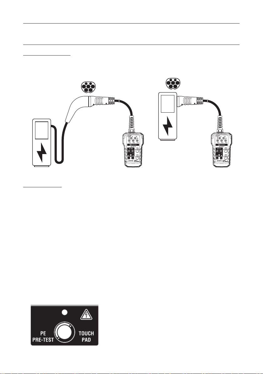
Fig.3-1
Examples of connection: to an EVSE with cable or to an EVSE without cable
Note: This adapter is designed for testing the EVSE Mode 3 for AC
charging only.

—
6
—
Available functions:
●Pre-Test
verifies that there is no presence of dangerous voltage at the
grounded PE terminal.
●CP (Control Pilot) state check
varies Control Pilot signal (resistance between CP-PE) to simulate
various vehicle states (A/B/C/D) for EVSE operation check.
●PP (Proximity Pilot) state check
varies Proximity Pilot signal (resistance between PP-PE) to imitate
various charge cables with different ratings for EVSE operation
check.
●CP (Control Pilot) signal error simulation
simulates the state that CP signal short-circuited to PE and confirm
that EVSE stops AC power flow.
●PE (Earth fault) Error simulation
simulates an interruption of PE conductor and confirm that EVSE
stops AC power flow.
● Phase voltage check LED
indicates the phase voltage of charge plug of EVSE.
●CP (Control Pilot) signal output terminal
is connected to an oscilloscope to analyze Control Pilot signal.
●Measuring terminal and mains socket
are available for various installation tests.
(Mains socket is dedicated to test EVSE connected to single phase
supply.)

—
7
—
4. Instrument layout
Fig.4-1
General descriptions
Name Description
(1) Measuring terminals Input terminals for measuring equipment
connection (N, PE, L1, L2, and L3)
(2) Live LED
Phase indicator LEDs for L1, L2, L3 terminals
(3) CP signal output terminal Output terminal (CP, PE) for CP (Control
Pilot) signal check
(4) Touch pad /
Pre-Test warning LED
Touch pad for Pre-Test/
Warning LED to indicate Pre-Test result
(5) PP state selector PP (Proximity Pilot) state rotary switch
selector (OPEN, 13A, 20A, 32A, 63A)
(6) CP state selector CP (Control Pilot) state rotary switch
selector (A, B, C, D)
(7) CP error simulation button
CP (Control Pilot) signal error simulation button
(8) PE error simulation button PE (Earth Fault) interruption error
simulation button
(9) EVSE connection plug
TYPE 2 plug connector to connect with EVSE
(10) Mains socket
For measurement instrument and load
connection (Particularly useful in case of
Single phase EVSE)
(11) Fuse compartment cover Cover for fuse compartment
—
8
—
5.Test procedures
5.1Connection
Connect EVSE connection plug of KEW 8602 to an EVSE to be tested
(with or without cable as the following examples).
5.2 Pre-Test
After connected with the EVSE under test, touch the touch pad (4)
with a bear finger. Normally the PE conductor is connected to ground
and has no voltage to ground. If a dangerous high voltage is present
at the PE conductor, Pre-Test warning LED (4) lights up. In such a
case, stop further testing immediately and check the wiring
connections. (e.g.: The PE conductor isn't connected to ground or is
connected to phase by mistake.)
* Pre-Test must be conducted prior to other tests.
* Touch the touch pad with a bare finger. Do not wear insulated
gloves.
Ensure a proper connection to the ground (though your shoes),
otherwise, warning indication with (4) Pre-Test warning LED may not
be reliable.
Fig.5-2
Fig.5-1

—
9
—
5.3CP (Control Pilot) state check
Switch the CP state selector (6) to simulate various vehicle state (A/
B/C/D) and check the behavior of EVSE.
Fig.5-3
1) Set the CP state selector (6) to position “A” (car not connected)
and connect KEW 8602 to EVSE.
2) Turn and set the CP state selector (6) to position “B” (car
connected).
(The EVSE under test may require payment information.)
3) Turn and set the CP state selector (6) to position “C” (car
charging) or “D” (car charging with ventilation).
Confirm that EVSE is ready for charging.
The phase indicators are LEDs, one LED for each phase. When
phase voltages are present at the EVSE, the LED indicators will
light up.
* LED L1 lights up when testing a single-phase circuit and LEDs
L1/ L2/ L3 light up for a three-phase circuit.
* In the case where the circuit under test doesn’t have a neutral
wire, no LED light up.
* If the EVSE isn’t ready for charging, turn the CP selector (6) to
“A” and wait for a few minutes. Then turn the CP selector (6) to
position C or D.
Tabla de contenidos


