KUMA K-AWD Manual de usuario

1
K-AWD | Rev. 231004
Model # K-AWD:
Applewood Cookstove
Tested and listed by OMNI-Test
Laboratories Inc.
Portland OR, USA
Safety tested to UL 1482-2022
Report # 0123WS015S
INSTALLATION AND OPERATING INSTRUCTIONS
SAVE THESE INSTRUCTIONS

Welcome to the Kuma family
Kuma is a modified version of the Greek word Kauma that means:
Burning, Glow, Heat (especially of the sun).
We would like to take the time to say thank you for purchasing a Kuma stove. We know
that there are many choices in hearth products, and we appreciate that you chose a Kuma for
your wood fire cooking and energy independence. Our mission is to provide you with a quality
product that will last a lifetime.
You may have noticed a portion of the Bible enclosed in your owner’s packet. It is a small
gift for you. Our faith in Jesus Christ is very important to us and we have that faith because
there is hope in heaven. That hope comes from the message of truth that is found in this New
Testament.
Thank you for allowing us the opportunity to warm your house and may God bless you.
Sincerely,
Mark & Lynnette Freeman
Founders - Kuma Stoves.

3
Please read this entire manual before you install and use your new room heater.
Failure to follow instructions may result in property damage, bodily injury, or
even death.
TABLE OF CONTENTS
SECTION 1 - SAFETY PRECAUTIONS
SECTION 2 - SPECIFCATIONS
SECTION 3 - INSTALLATION INSTRUCTIONS
SECTION 4 - OPERATING INSTRUCTIONS
SECTION 5 –COOKING INSTRUCTIONS
SECTION 6 - MAINTENANCE
SECTION 7 - TROUBLESHOOTING
SECTION 8 - WARRANTY

4
SECTION 1 - WARNINGS
WARNING
If this stove is not properly installed, a house fire can occur. For your protection, follow the installation
instructions provided. We recommend contacting local building or fire officials regarding restrictions and
installation inspection requirements in your area. We also recommend that your Kuma stove be installed by a
properly trained and licensed installer, preferably an NFI (National Fireplace Institute) expert.
DO NOT CONNECT THIS UNIT TO A CHIMNEY FLUE SERVICING ANOTHER APPLIANCE.
Do not burn garbage or flammable fluids such as gasoline, naptha or engine oil. Do not use charcoal lighter
fluid or similar liquids to start or “freshen up” a fire in this stove. Keep all such fluids well away from the stove
while in use. Storing these fluids near a stove could cause a fire.
DO NOT CONNECT TO ANY AIR DISTRIBUTION OR DUCT SYSTEM.
DO NOT OVERFIRE. If any part of the stove or chimney glows, the stove is in an over fire condition. If this
happens, shut the air control off immediately. Over firing can cause damage.
WARNING: DO NOT INSTALL IN A SLEEPING ROOM OF A MOBILE HOME.
An improperly drafting stove can cause smoke and carbon monoxide to enter the home. Smoke detectors and
carbon monoxide monitors are recommended to be installed in the same room as this stove.
CAUTION: THE STRUCTURAL INTEGRITY OF THE FLOOR, WALLS, ROOF/CEILING, AND VAPOR BARRIERS
MUST BE MAINTAINED.
DO NOT USE SINGLE WALL PIPE OR CONNECTOR PIPE FOR ANY CHIMNEY APPLICATION, EXTERIOR OR
THROUGH THE WALL OR CEILING. Single wall pipe may only be used as a connection between the stove and an
approved masonry or stainless steel chimney. Single wall pipe may not be used as a connector in mobile
homes.
When installing into an existing masonry or metal chimney, examine the chimney system carefully. If you have
any questions, seek professional advice. We recommend having existing chimneys cleaned and inspected by a
qualified professional prior to the installation of your new stove.
NOTE ALL MINIMUM CLEARANCE REQUIREMENTS TO COMBUSTIBLES. Installation must comply with
minimum clearances as listed in this manual. Clearances may only be reduced by means approved by the
regulatory authority.
Do not operate this stove with the door in an open position, except for cracking open during start-up. Continued
operation with the door open can cause overheating of the unit, and expose embers to nearby combustibles.
Do not operate with broken glass. Do not abuse glass such as striking or slamming the door.
This stove must be connected to a minimum 6” diameter listed chimney that complies with U.L. type 103HT
factory built chimney or a code approved masonry chimney. When installing into masonry chimneys, a U.L. 1777
approved liner must be installed. TO BE IN-STALLED AS A FREESTANDING COOK STOVE WITH THE
CLEARANCES IN THE MANUFACTURER'S INSTALLATION INSTRUCTIONS. NOT TO BE INSTALLED IN ANY
FACTORY-BUILT FIREPLACE.
When connecting single wall or double wall connector pipe to the stove and chimney, use 3 screws per pipe joint
including 3 screws securing the pipe to the stove. Depending on the type of double wall pipe you are using, it may
also be necessary to fasten it at the chimney.
Use only approved components for Chimney and Connector. Field fabricated or “makeshift” components are not
allowed and can cause a fire.
When connecting this stove to a masonry chimney, make sure you observe all applicable clearances including
walls, ceilings and other combustible material. A masonry chimney must be minimum 6” diameter and
constructed with a liner according to NFPA code 211. If you have any questions about the condition or the code
compliance of your masonry chimney, please speak with a qualified professional.
HOT WHILE IN OPERATION. KEEP CHILDREN, CLOTHING AND FURNITURE AWAY. CONTACT MAY CAUSE
SKIN BURNS.
DO NOT PUT WOOD OR ANY COMBUSTIMBLE MATERIAL IN THE STORAGE AREA UNDER THE
STOVE.

5
SECTION 2 - SPECIFICATIONS
CERTIFICATION TAG

6
APPLEWOOD DIMENSIONAL DRAWINGS
All dimensions are in inches.
Cookware Storage:
Do not store wood
here.
7
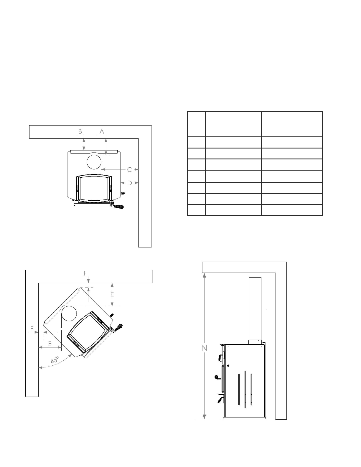
MINIMUM CLEARANCE REQUIREMENTS
Pipe clearances are measured to the outside diameter of the pipe. Stove clearances are measured to the top
plate of the stove. Pipe diameter will vary by brand so when planning your installation, make sure the stove
clearances AND the pipe clearances are equal to or greater than the minimum clearances. Always follow
local building codes. These clearances may be reduced only by using approved methods found in NFPA 211.
If you are installing the optional side shelves, all clearances to the stove remain the same as measured to the
top plate of the stove. You cannot install the stove at minimum corner clearance with the side shelves
attached: this is a physical impossibility. The side shelves can be installed with zero clearance to the walls.
*any ceiling height lower than 72” is considered an alcove
installation, see alcove requirements below.
Minimum
Clearance with
single-wall pipe
Minimum clearance
with double-wall
pipe
A
7
6.5
B
5
5
C
15.75
15.25
D
7.5
7.5
E
9.75
9.25
F
2
2
N*
84
72

8
ADDITIONAL CLEARANCE REQUIREMENTS FOR ALCOVE INSTALLATIONS
Minimum
Clearance with
single-wall pipe
Minimum clearance
with double-wall
pipe
B
Not Allowed: Must
use double wall for
alcove installation
5
L
12
12
M
Not Allowed: Must
use double wall for
alcove installation
38
P
Not Allowed: Must
use double wall for
alcove installation
60
(72 if wall exit)
R
18
Follow pipe
manufacturer’s
instructions.
Side view of wall exit Installation
Side view of Alcove Installation
Front View of Alcove Installation
ADDITIONAL CLEARANCE REQUIREMENTS FOR WALL EXIT INSTALLATIONS

9
SECTION 3 –INSTALLATION INSTRUCTIONS
FLOOR PROTECTION REQUIREMENTS
Floor protection must be non-combustible. Floor protection must be underneath the stove and extend to the
sides and front of the stove as shown below. Side protection (G) is measured to the top plate of the stove.
Front protection (H) is measured to the firebox face of the stove.
G
H
Type
3.25”
16”
Type 1 (ember protection) No insulation R-value required.
*Through Wall Installations: Hearth must extend underneath and 2” to either side of the horizontal
connector pipe.
It is highly recommended that this stove is installed by a qualified professional certified by the
National Fireplace Institute.
The structural integrity of the floor, walls and ceiling/roof must be maintained. Use additional
bracing if required. Never cut a load bearing wall or engineered truss.
NEVER INSTALL A STOVE IN A SLEEPING ROOM
This stove is heavy: Get help from another person and use proper lifting techniques
*

10
STOVE ASSEMBLY
Your stove comes almost fully assembled and screwed down to the wooden shipping crate. Using a 5/16”
socket wrench, remove the 4 screws from base of the stove. Place the stove onto your hearth taking care not
to scratch the hearth. Open the box located in the base of the stove and complete the assembly as follows:
Place the rear shield on the bottom of the oven at
the back. The shield fits between the side wall of the
oven with the flanges facing down.
Place the front sliding heat shield on the bottom of
the oven at the front. Orient the 2 square cut-outs
towards the front of the oven. You can then use the
oven tool to slide the shield forward and backwards.
Slide the shield all the way to the front of the oven
for baking and home heating. Slide the shield
backwards to expose the high-heat zone of the oven
for boiling or frying.
Slide the rear rack to the back of the oven on the
lower oven rail. You can move the racks to the upper
rail anytime that you would like.
Tabla de contenidos


