Kioti DK35SE Manual de usuario

STEERING SYSTEM
DK35SE/DK40SE/DK45SE/DK50SE
TABLE OF CONTENTS
1. SPECIFICATIONS ................................... 9-2
1.1 Steering cylinder ......................................8-2
1.2 Steering unit .............................................8-2
1.3 Tightening torque for main components ... 8-2
2. OPERATING PRINCIPLE........................ 9-3
2.1 Diagram for steering operation ................. 8-3
2.2 Operating principle ...................................8-5
2.3 Structure ................................................... 8-9
3. TROUBLESHOOTING .......................... 9-12
4. MEASUREMENT AND ADJUSTMENT. 9-13
4.1 Steering relief opening pressure ............... 8-13
4.2 Relief pressure adjustment ....................8-13
4.3 Toe in ...................................................... 8-14
5. EXPLODED VIEW................................. 9-15
5.1 T595A steering cylinder ..........................8-15
5.2 T596A steering cover .............................8-16
5.3 T605A steering unit ................................8-17
5.4 T875A instrument panel cover ............... 8-18
5.5 T845A-1 frame (HST) ............................. 8-19
5.6 T845A-2 frame (mechanical) .................. 8-20
6. SERVICING............................................ 9-21
6.1 Steering cylinder ....................................8-21
6.2 Removal of steering unit ........................8-22
6.3 Tightening torque of steering hose and
installation of steering unit ..................... 8-23
6.4 Steering hose location ............................ 8-24
6.5 Disassembly of steering unit
components ............................................ 8-26
M32_EN_A4.indb 1 2007-02-02 오전 10:44:43
9-2 DT66-W00 Jan. 2007
DK35/40/45/50SE
SAFETY FIRSTGENERALENGINECLUTCHTRANSMISSIONHSTREAR AXLEBRAKEFRONT AXLEHYDRAULICELECTRIC STEERING
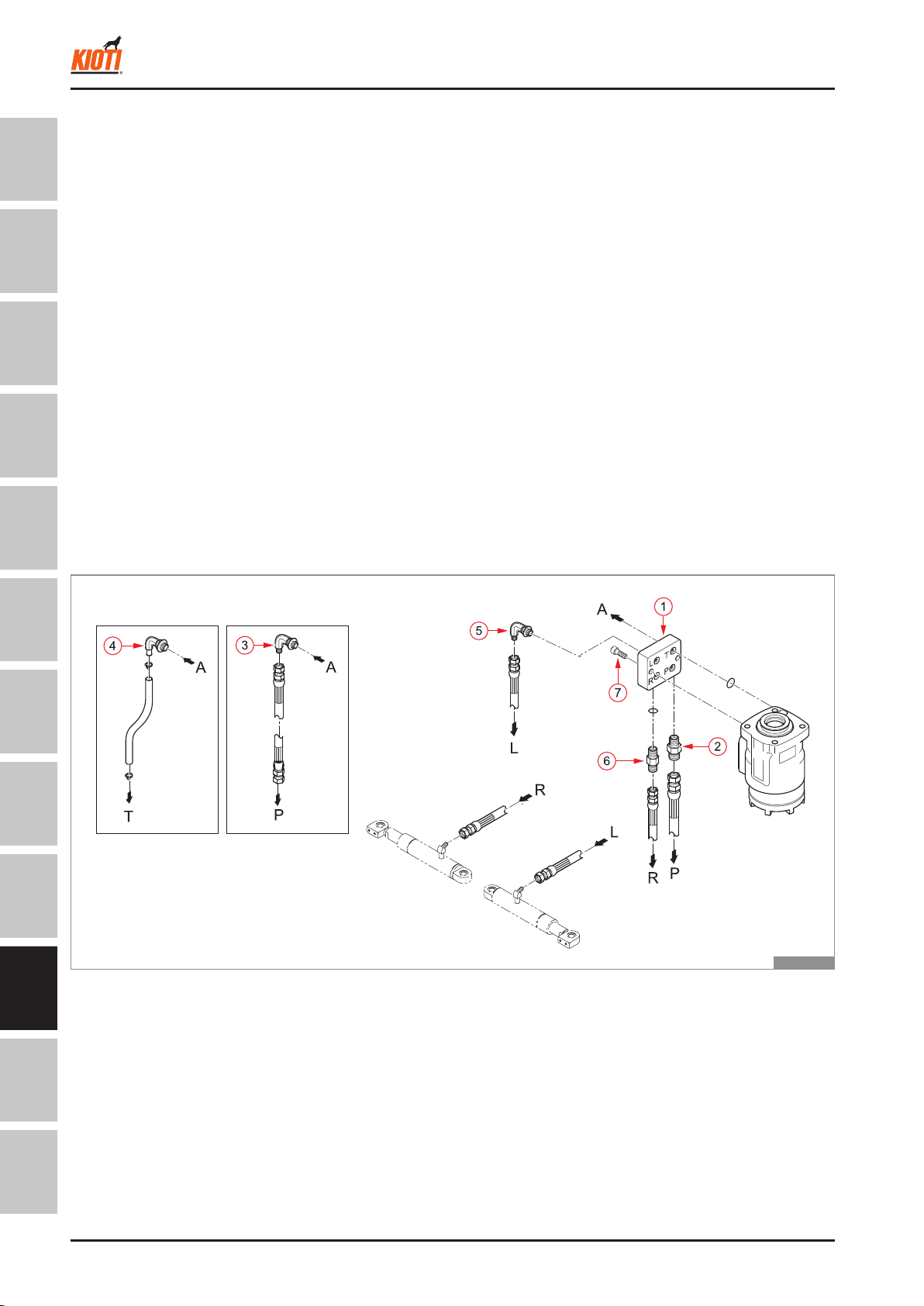
Connectors (2, 3, 4, 5, 6) that are connected to each port (P, T, L, R) of
hydraulic block (1)..................49 Nm, 5 kgf-m, 36.1 lb-ft
Hydraulic hoses (RH, LH) ......24.5 Nm, 2.5 kgf-m, 18 lb-ft
Socket head bolt (7)...............44.1 Nm, 4.5 kgf-m, 32.5 lb-ft
Hydraulic hoses (P) ...............49 Nm, 5 kgf-m, 36.1 lb-ft
Steering wheel nut .................48 ~ 55.9 Nm, 4.9 ~ 5.7 kgf-m, 35.4 ~ 41.2 lb-ft
1.
2.
3.
4.
5.
1. SPECIFICATIONS
1.1 STEERING CYLINDER
기계식 HST식
T46W901A
Type .......................................Two cylinders with one rod single action (ram cylinder)
Cylinder O.D. .........................35 HP = 60 mm (2.3 in.), 40 ~ 50 HP = 65 mm (2.5 in.)
Cylinder I.D. ...........................35 HP = 55 mm (2.1 in.), 40 ~ 50 HP = 60 mm (2.3 in.)
Rod O.D. ................................35 HP = 40 mm (1.5 in.), 40 ~ 50 HP = 45 mm (1.7 in.)
Cylinder stroke .......................198.5 mm (7.8 in.)
Max. steering angle ...............55 ± 1.0°
1.2 STEERING UNIT
Type .......................................Non-load reaction type
Steering output ow rate ........35 HP = 69 cc/rev, 40 ~ 50 HP = 96 cc/rev
Relief valve pressure .............140 kgf/cm2(1,988 PSI)
Rated input ow rate ..............23ℓ/min (9 gpm)
Pump capacity (2nd pump) ....10 cc/rev.
1.3 TIGHTENING TORQUE FOR MAIN COMPONENTS
1.
2.
3.
4.
5.
6.
1.
2.
3.
4.
5.
Mechanical HST
STEERING SYSTEM - SPECIFICATIONS
M32_EN_A4.indb 2 2007-02-02 오전 10:44:44
SAFETY FIRSTGENERALENGINECLUTCHTRANSMISSIONHSTREAR AXLEBRAKEFRONT AXLEHYDRAULICELECTRIC STEERING
DT66-W00 Jan. 2007 9-3
DK35/40/45/50SE
2. OPERATING PRINCIPLE
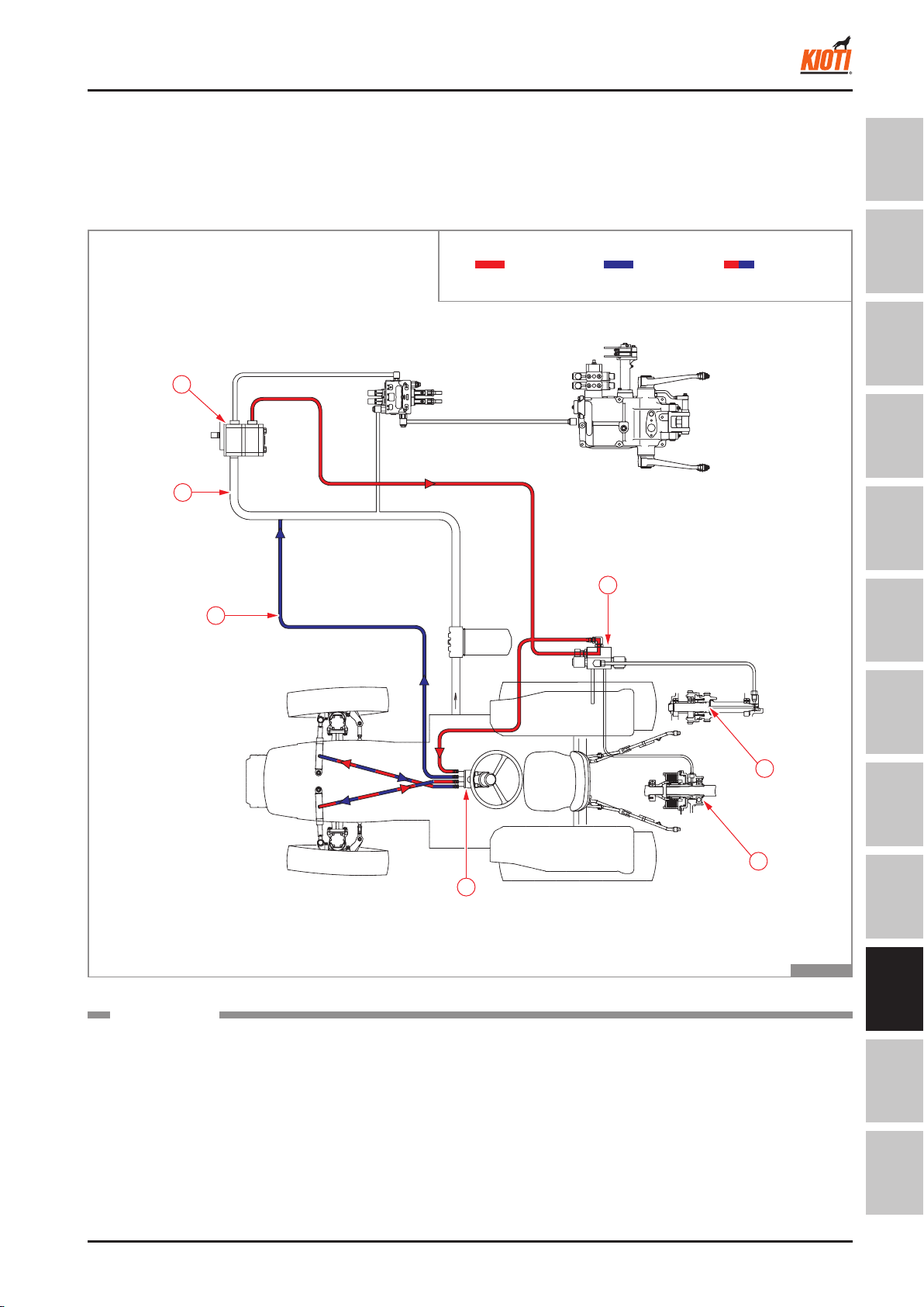
2.1 DIAGRAM FOR STEERING OPERATION
MECHANICAL
▶
The oil supplied from the gear pump (1) is sent to the
modulator (2) to provide the pressure for the operation
of PTO (3) or 4WD (4). Then, it is supplied to the steer-
ing unit (5).
2
IN T
6
7
1
5
3
4
T46W902A
Pressure Return
Operating
hydraulic
pressure
(1) Gear pump
(2) Modulator valve
(3) PTO clutch pack
(4) 4WD clutch
(5) Steering unit
(6) Steering return pip
(7) Suction pipe
COMPONENTS
The oil ows to the left or right steering cylinder depend-
ing on the rotated position of the steering wheel. Then,
the other cylinder that is not supplied with oil is com-
pressed by the tie rod. The oil is return to the gear pump
suction line (7) through the return line (6) and recirculated.
RETURN
RETURN
STEERING SYSTEM - OPERATING PRINCIPLE
M32_EN_A4.indb 3 2007-02-02 오전 10:44:45

9-4 DT66-W00 Jan. 2007
DK35/40/45/50SE
SAFETY FIRSTGENERALENGINECLUTCHTRANSMISSIONHSTREAR AXLEBRAKEFRONT AXLEHYDRAULICELECTRIC STEERING
For the HST type, the route that the oil is supplied to
the steering unit is the same. However, the return line (1)
supplies oil to the HST (4) through the HST oil cooler
and the HST lter (3) for charging of the HST.
HST
▶
T46W903A
(1) Oil cooler pipe (2) Oil cooler (3) HST lter (4) HST
COMPONENTS
Pressure Return
Operating
hydraulic
pressure
STEERING SYSTEM - OPERATING PRINCIPLE
M32_EN_A4.indb 4 2007-02-02 오전 10:44:47

SAFETY FIRSTGENERALENGINECLUTCHTRANSMISSIONHSTREAR AXLEBRAKEFRONT AXLEHYDRAULICELECTRIC STEERING
DT66-W00 Jan. 2007 9-5
DK35/40/45/50SE
2.2 OPERATING PRINCIPLE
Overviews
This tractor has the full hydraulic, non-load reaction
type steering system.
The full hydraulic type completely relies on the hydrau-
lic oil for transferring the power between the steering
unit and the steering cylinder. It is not equipped with
any mechanical transferring system, such as a drag
link, pitman arm, rack or pinion. Therefore, the angles
of the steering wheel and the front wheels are not xed
each other.
T46W904A
A
140kgf/cm2
흡입
점검 밸브
The connection of the section (A) distinguishes the load
reaction and the non-load reaction.
For the load reaction type, when one steering cylinder
is compressed by the outer force applied to the front
wheel while driving, the returned oil turns the gerotor of
the steering unit which then turns the steering wheel.
Then, the oil ows to the other cylinder.
T46W905A
A
140kgf/cm2
흡입
점검 밸브
Circuit diagram for non-load reaction type
: DK 35/40/45/50 SE
Circuit diagram for load reaction type
: CK and conventional DK series
Therefore, when releasing the steering wheel after cor-
nering, the steering wheel is automatically returned to
the center position and the tractor moves straight for-
ward or backward. This is convenient for the high-speed
driving, but the steering wheel should be held to keep
the steering angle and the noise and vibration is severe
than the non-load reaction type. Therefore, this tractor
is equipped with the non-load reaction type to enhance
the operational convenience and minimize the noise
and vibration.
INLET
CHECK V/V
INLET
CHECK V/V
STEERING SYSTEM - OPERATING PRINCIPLE
M32_EN_A4.indb 5 2007-02-02 오전 10:44:48

9-6 DT66-W00 Jan. 2007
DK35/40/45/50SE
SAFETY FIRSTGENERALENGINECLUTCHTRANSMISSIONHSTREAR AXLEBRAKEFRONT AXLEHYDRAULICELECTRIC STEERING
Operation
When the steering wheel is not moved, the valve plate
(3) keeps its neutral position by the centering spring (4).
In this case, the oil ows to the P port through the mod-
ulator. Then, it is directly sent to the T port and then
returned to the middle of the suction pipe (oil cooler for
HST).
The steering angle is maintained unless the steering
wheel is turned since the RH and LH lines to the steer-
ing cylinder are blocked. Therefore, the steering wheel
is not returned to the center position when releasing it
after cornering.
NEUTRAL
▶
T46W906A
The steering should be forced to be turned in some oc-
casions, for example, when the engine does not start
or the hydraulic pump is damaged.
When turning the steering wheel to the right direction,
the RH oil passage of the valve plate is open and the
oil is supplied to the R port and the RH cylinder by the
gerotor. Then, the drained oil by the compressed LH
cylinder is returned to the valve plate and supplied to
the gerotor inlet again through the check valve (1).
Therefore, the steering is possible by the recirculation
of the oil in the steering unit and the steering cylinder
even when the oil is not supplied from the gear pump.
MANUAL STEERING (RIGHT TURN)
▶
TP
RL
T46W907A
STEERING SYSTEM - OPERATING PRINCIPLE
M32_EN_A4.indb 6 2007-02-02 오전 10:44:49

SAFETY FIRSTGENERALENGINECLUTCHTRANSMISSIONHSTREAR AXLEBRAKEFRONT AXLEHYDRAULICELECTRIC STEERING
DT66-W00 Jan. 2007 9-7
DK35/40/45/50SE
RIGHT TURN
▶
When turning the steering wheel in the right direction,
the gerotor rotates and the valve plate is moved to the
right side so that the gerotor (1) rotates further by the
oil from the P port. Then the oil is supplied to the right
cylinder through the R line so that the steering wheel
can be turned with only small amount of force. When
the right cylinder is expanded, the power is transferred
to the tie rod (2) and the left cylinder is compressed.
Therefore, the oil returned to the left cylinder is re-
turned to the T port through the L port and the valve
plate.
TP
RL
T46W908A
OPERATION OF RELIEF VALVE (FOR
RIGHT TURN)
▶
If the steering cylinder rod is completely drawn out and
does not move, the rod does not move due to the stop-
per even when its stroke is not complete or the wheels
do not move due to the excessive load on the steering,
the relief valve (140 kg-f/cm2) is open to drain the oil
from the P port to the T port immediately.
TP
RL
1
T46W909A
STEERING SYSTEM - OPERATING PRINCIPLE
M32_EN_A4.indb 7 2007-02-02 오전 10:44:50

9-8 DT66-W00 Jan. 2007
DK35/40/45/50SE
SAFETY FIRSTGENERALENGINECLUTCHTRANSMISSIONHSTREAR AXLEBRAKEFRONT AXLEHYDRAULICELECTRIC STEERING
The operation for the left turn is same as that of right
turn except for the oil ow direction.
LEFT TURN
▶
T46W910A
STEERING SYSTEM - OPERATING PRINCIPLE
M32_EN_A4.indb 8 2007-02-02 오전 10:44:51

SAFETY FIRSTGENERALENGINECLUTCHTRANSMISSIONHSTREAR AXLEBRAKEFRONT AXLEHYDRAULICELECTRIC STEERING
DT66-W00 Jan. 2007 9-9
DK35/40/45/50SE
2.3 STRUCTURE
Structure and major specications for steering cylinder
The steering system for this tractor has two single act-
ing cylinders. It provides the same steering rpm (for left
and right turn) and the operational feeling of the steer-
ing wheel. The outer force for cylinder rod compression
is supplied by the tie rod since this is the single action
type.
Type Tube O.D. (C) Tube I.D. (B) Rod O.D (A) Stroke (D)
35HP φ 60 (2.36 in.) φ 55 (2.16 in.) φ 40 (1.57 in.) 198.5 mm (7.81 in.)
40 ~ 50HP φ 65 (2.56 in.) φ 60 (2.36 in.) φ 45 (1.77 in.) 198.5 mm (7.81 in.)
MAJOR SPECIFICATIONS
▶
STRUCTURE
▶
T46W911A
(1) Tube
(2) Packing
(3) Bush
(4) Dust seal
(5) Rod
(6) Ring
(7) Housing
(8) Bearing
(9) Snap ring
(A) Rod O.D
(B) Tube I.D
(C) Tube O.D
(D) Stroke
COMPONENTS
STEERING SYSTEM - OPERATING PRINCIPLE
M32_EN_A4.indb 9 2007-02-02 오전 10:44:51
9-10 DT66-W00 Jan. 2007
DK35/40/45/50SE
SAFETY FIRSTGENERALENGINECLUTCHTRANSMISSIONHSTREAR AXLEBRAKEFRONT AXLEHYDRAULICELECTRIC STEERING
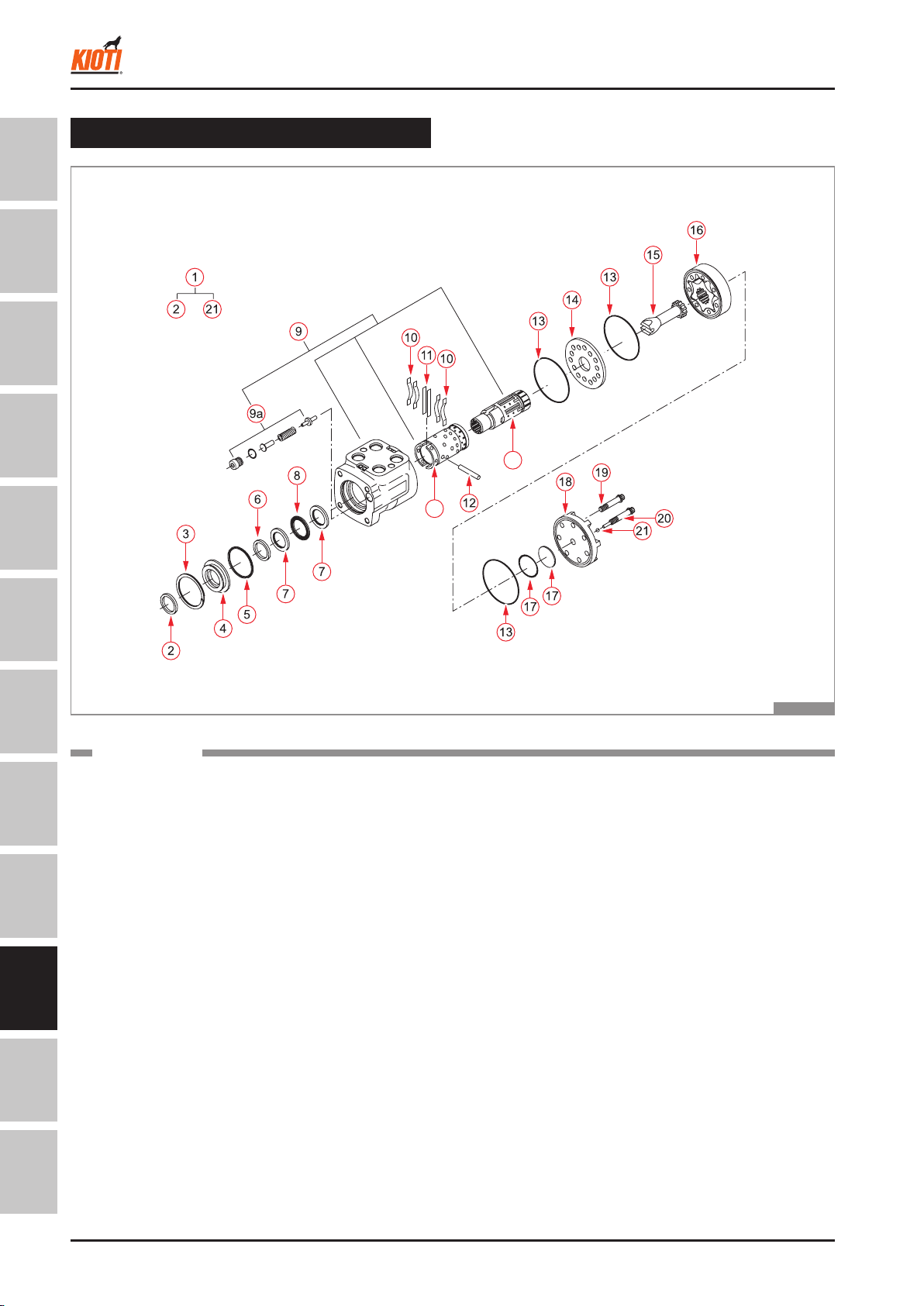
Steering unit
23
22
T46W912A
(1) Steering case assembly
(2) Dust seal
(3) Retainer ring
(4) Seal gland bushing
(5) O-ring
(6) Oil seal
(7) Lace bearing
(8) Thrust needle bearing
(9) Control valve assembly
(9a) Relief valve
(10) Centering spring
(11) Plain spring
(12) Pin
(13) O-ring
(14) Spacer
(15) Drive (shaft)
(16) Gerotor
(17) Star seal assembly
(18) Endcap
(19) Bolt
(20) Retainer bolt assembly
(21) Ball
(22) Spool
(23) Sleeve
COMPONENTS
STEERING SYSTEM - OPERATING PRINCIPLE
M32_EN_A4.indb 10 2007-02-02 오전 10:44:52
Otros manuales para DK35SE
1
Este manual sirve para los siguientes modelos
3
Tabla de contenidos
Otros manuales de Vehículo utilitario de Kioti


