Kinco MK Series Manual de usuario

Kinco-MK
User Manual
1
CONTENT
Chapter 1 General Introduction ................................................................................................... 3
1.1 Summary ............................................................................................................................ 3
1.2 Product List ........................................................................................................................ 3
1.3 Environmental Condition ...................................................................................................3
1.4 specification ........................................................................................................................5
1.4.1 display specification .................................................................................................... 5
1.4.2 PLC specification .........................................................................................................6
1.4.3 Appearance ............................................................................................................... 7
1.4.4 Dimension .................................................................................................................8
Chapter 2 PLC Introduction ........................................................................................................ 9
2.1 Functions ............................................................................................................................ 9
2.1.1 CPU Status and LEDs ..................................................................................................9
2.1.2 USB Programming port ............................................................................................... 9
2.1.3 Serial Communication Port ....................................................................................... 10
2.1.4 High Speed Counter and High Speed Pulse Output ..................................................11
2.1.5 Edge Interrupts ...........................................................................................................11
2.1.6 Data Retentive and Data Backup ...............................................................................11
2.1.7 Real-time Clock (RTC) ............................................................................................. 13
2.1.8 Backup Battery .......................................................................................................... 13
2.2 Wiring diagram .................................................................................................................14
2.3 Dimension ........................................................................................................................ 17
2.4 Technical Specification .................................................................................................... 17
Chapter 3 Software Introduction ............................................................................................... 19
3.1 HMI programming ........................................................................................................... 19
3.1.1 Create project .............................................................................................................19
3.1.2 Edit configuration . ................................................................................................. 21
3.1.3 download link for HMI manual ..............................................................................21

Kinco-MK
User Manual
2
3.2 PLC ...................................................................................................................................22
3.2.1 introduction ................................................................................................................22
3.2.2 Install driver of USB programming port ................................................................... 22
3.2.3 High speed counter .................................................................................................... 33
3.2.3.1 Operation Modes and Inputs of the High-speed Counters ..................................34
3.2.3.2 Control Byte and Status Byte ................................................................................. 35
3.2.3.3 Preset value (PV value) setting ...............................................................................37
3.2.3.4 “CV=PV” Envent No. .............................................................................................39
3.2.3.5 How to use high speed counter ...............................................................................40
3.2.4 How to use high speed pulse output .......................................................................... 41
3.2.4.1 High speed pulse output instruction ....................................................................... 42
3.2.4.2 How to use PLS instruction ....................................................................................42
3.2.4.2.1 High-speed Pulse Output Function of HMI-PLC .........................................43
3.2.4.2.2 PTO/PWM Register ......................................................................................45
3.2.4.2.3 PTO Operations ......................................................................................... 47
3.2.4.2.4 PWM Operations .......................................................................................... 49
3.2.5 How to Use Position Control Instructions ..............................................................50
3.2.5.1 How to Modify the Current Value of Position Control Instructions ...................... 50
3.2.5.2 Can it change maximum output frequency when position control instruction is
executing? ........................................................................................................................... 52
3.3 The use of analog quantities .............................................................................................53
3.3.1 Wiring diagram .......................................................................................................53
3.3.2 Measurement Ranges and The measured value Representation ............................... 53
3.3.3 Configuration in software ..........................................................................................54

Kinco-MK
User Manual
3
Chapter 1 General Introduction
1.1 Summary
Kinco MK series combines the superior technology of Kinco HMI and PLC and the
Internet of Things (M-IoT). It is an economical all-in-one machine product that supports the
Internet of Things functions launched by Kinco Company.
The Kinco MK series all-in-one HMI-PLC retains the high cost performance of the
Kinco HP series of all-in-one machines, but adopts a high-performance CPU and the new
DTools software technology platform for programming the HMI, so as to support more rich
picture components and functions of the new software. In addition, combined with the Kinco
M-IoT technology platform it provides remote download, pass through PLC communication
over the network, VNC remote monitoring, equipment management and other advanced
remote operation and maintenance functions. This will provide more value for our users.
1.2 Product List
Item
Type
Specification
MK070
MK070E-33DT
DC24V,DI 16*DC24V,DO 14*DC24V,2*AI,1*AO,USB2.0
Programming port (PLC&HMI sharing same programming port).
PLC Part share 2*RS485 COM port, Supports up to 8 KS series
expansion modules. HMI part provides Ethernet interface,
supports access to external network or other Ethernet devices.
MK070E-32DX
DC24V ,DI 16*DC24V ,DO 4*DC24V and 12*Relay.USB2.0
Programming port (PLC&HMI sharing same programming port)
PLC part 2*RS485 COM port, Supports up to 8 Kinco KS series
expansion modules. HMI part provides Ethernet interface,
supports access to external network or other Ethernet devices.

Kinco-MK
User Manual
4
MK043
MK043E-20DT
DC24V,DI 9*DC24V,DO 9*DC24V,2*AI (only support voltage
type),USB2.0 Programming port (PLC&HMI sharing same
programming port) PLC part 2*RS485 COM port, Supports up to
8 Kinco KS series expansion modules. HMI part provides Ethernet
interface, supports access to external network or other Ethernet
devices.
1.3 Environmental Condition
Kinco MK series accords with GB/T 15969.3-2007(idt IEC61131-2:2007)standard and test
specifications.
The following table lists the conditions and requirements for MK series to work properly. It is
the user's responsibility to ensure that the service conditions are not exceeded.
Transport and storage
Ambient
conditions
temperature
-10℃~+60℃
relative
humidity
10%~95%, no condensation
Altitude
Up to 3000 m
Mechanical
conditions
Free falls
within manufacturer's original packaging, 5 falls from 1m
of height.
Normal Operation
Ambient
conditions
air
temperature
Open equipment : -10 --- +55°C; Enclosed equipment: 0~
50℃
relative
humidity
10%~95%, no condensation
Altitude
Up to 2000 m
Pollution
degree
for use in pollution degree 2.
Mechanical
conditions
Sinusoidal
vibrations
5<f<8.4Hz, Occasional: 3.5mm amplitude; Continuous:
1.75mm amplitude.
8.4<f<150, Occasional: 1.0g acceleration; Continuous:
0.5g acceleration.
Shock
occasional excursions to 15g, 11 ms, half-sine, in each of 3
mutually perpendicular axes.
Kinco-MK
User Manual
5
Electromagnet
ic
compatibility
(EMC)
Electrostatic
discharge
±4kV Contact, ±8kV Air. Performance criteria B.
High energy
surge
a.c. main power: 2KV CM, 1KV DM;
d.c. main power: 0.5KV CM, 0.5KV DM;
I/Os and Communication port: 1KVCM.
Performance criteria B.
Fast transient
bursts
main power: 2KV,
5KHz.
I/Os and Communication port:
1KV,
5KHz.
Performance criteria B.
Voltage drops
and
interruptions
a.c. supply: at 50Hz, 0% voltage for 1 period; 40% voltage
for 10 periods; 75% voltage for 20 periods.
Performance criteria A.
Ingress Protection Rating
IP65
1.4 specification
1.4.1 display specification
Type
MK070E-33DT
MK070E-32DX
MK043E-20DT
LCD size
7” TFT
4.3” TFT
Resolution
800*480
480*272
Color
256K colors
Brightness
250cd/m2
400cd/m2
Back light
LED
Touch panel
4 lines,resistor web(4H)
Life
50000 hours
Processor
700MHz RISC
Ethernet
10M/100M self-adaption
Memory
128MB Flash + 64MB DDR2 RAM
Recipe memory
256KB+RTC
Expansion memory
1 USB Host
Programming download
1*USB Slave/Ethernet/USB Flash disk

Kinco-MK
User Manual
6
Printer port
USB
Software
DTools programming + EdgeAccess for remote services + Kinco
Miot for IoT function
1.4.2 PLC specification
Parameters
MK070E-33DT
MK070E-32DX
MK043E-20DT
Power supply
Rated voltage
DC24V
Voltage range
DC20.4V-28.8V
I/O communication
Digital IO
DI 16*DC24V,
DO 14*DC24V
DI 16*DC24V,
DO 4*DC24V+12*Relay
DI 9*DC24V,
DO 9*DC24V
Analog IO
2*A,1*AO.
(Supports voltage and
current type)
None
2*AI
(only support voltage
type)
Expansion
Up to 8 module;Support KS series expansion module
Programming port
USB2.0 Slave
Serial port
2*RS485, PORT1&PORT2, Baudrate up to 115.2kbps.
Port 1:Support programing, Modbus RTU master and slave,Free protocol
Port 2: Modbus RTU master and slave,Free protocol
High speed counter
4
Support single,double UP/DOWN,AB phase pulse input.
4 max 50KHz.
High speed output
4
Q0.0,Q0.1,Q0.4 max output 50 Khz(The load resistance must be less than
3KΩat maximum frequency)
Q0.5 max output 10Khz.

Kinco-MK
User Manual
7
Interrupt
4,I0.0-I0.3 can be on/off interrupt.
Memory area
Programming
Max. 4K instruction
Users data
M area 1K bytes;V area 4K bytes
Data backup
E2PROM,448 bytes
Retentive range
V area 2K bytes:VB0-VB1907 ;C area :C0-C63.
3 year at normal temperature
Others
RTC
256
1ms time base:4
10ms time base:16
100ms time base:236
Interrupt
2,0.1ms time base.
Counter
256
RTC
Yes. The difference is less than 5min/month at 25℃.
1.4.3 Appearance
Display and touch
Indicator light

Kinco-MK
User Manual
8
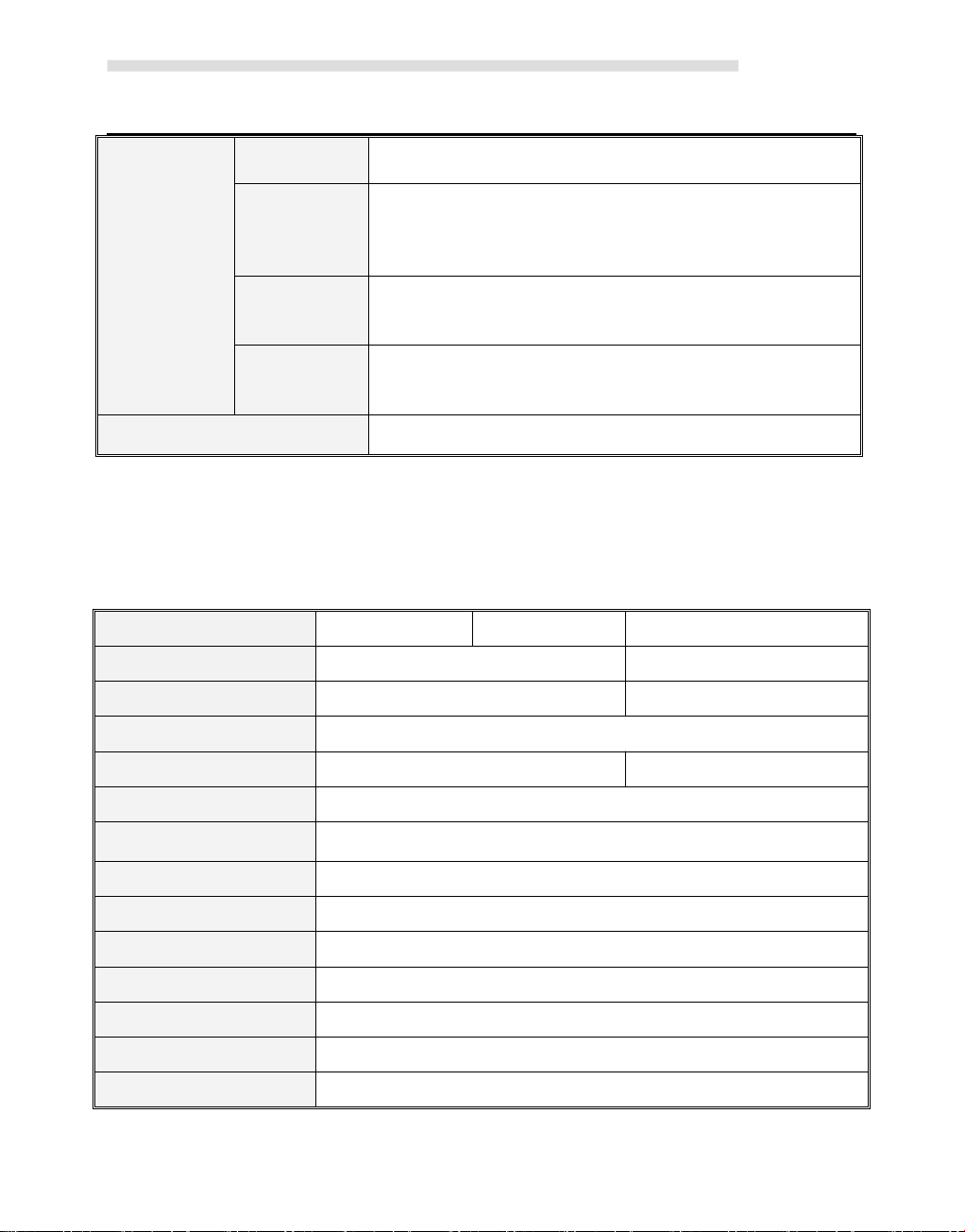
1.4.4 Dimension
MK070E-33DT
MK070E-32DX
MK043E-20DT
Dimension
204*150*38.55mm
132*102*31.5mm
Cutout size
192*138mm
119*93mm
DI
AI
DO
AO
DC24V
2*RS485 Ports
and EX. (PLC)
USB Host
USB Programming
Port(HMI&PLC)
Ethernet Port (HMI)
Clear Program (PLC)

Kinco-MK
User Manual
9
Chapter 2 PLC Introduction
2.1 Functions
2.1.1 CPU Status and LEDs
The CPU has two modes: STOP mode and RUN mode.
In RUN mode, the CPU executes the main scan cycle and all interrupt tasks.In STOP mode,
the CPU only process communication requests which comes from KincoBuilder software and
other Modbus RTU master device.At the same time, all output points are immediately output
to the "stop output" value defined in [Hardware Configuration] of the user project.
Change CPU status
HMI-PLC provides one way for manually changing the CPU status: Executing [RUN] or
[STOP] in Kincobuilder.
Usually when the PLC is power on, default status of PLC is RUN status.
Below situation, the PLC status depend on Kincobuilder programming
a— PLC RUN mistake (strong mistake) will stop the PLC
b— The user use Kincobuilder [setup], PLC is RUN/STOP status
c— Users use STOP instruction to stop PLC
d— If downloading project failed, PLC will keep STOP status.
2.1.2 USB Programming port
HMI-PLC uses USB (USB2.0 ) port as programming port. This type of interface is consistent
with most Kinco HMI products. Users can use cables with same connector port for PLC
programming.The USB programming port of MK070E PLC and HMI are sharing one.

Kinco-MK
User Manual
10
In PC, the programming port of HMI-PLC will be a virtual COM port, you must install the
driver for it when using in PC first time. After finishing installing software Kincobuilder ,
there will be different drivers in the path “\Kincobulider V***\Drivers\” for different versions
of Windows system. Right now it can only support Windows XP, Windows 7,Windows 8 and
Windows 10. When connecting programming cable to HMI-PLC and PC first time, Windows
system will detect new hardware and mention installing driver, users can install the driver
according to the version of Windows.
When the first time using USB cable to download Program on MK series.The USB driver is
needed installation.The installation step please refer to Kinco HPbuilder [Help]-[User
Manual]--Chapter 2.10
2.1.3 Serial Communication Port
Kinco MK series providing 2*RS485 COM,which is Port1 and Port2,the Baudrated up to
115.2Kbps. Port1 could use as programming port,as well as Modbus RTU Master/Slave
protocol,and free communication. Port2 could use as Modbus RTU Master/Slave protocol,free
communication.
And please refers to 2.2 Wiring diagram to know about their pin assignment.
Otros manuales para MK Series
1
Este manual sirve para los siguientes modelos
3
Tabla de contenidos


