KI WireWorks Manual de usuario

Assembly Instructions
WireWorks® Panel System
January 2020

A

WireWorks® Panel System - Table of Contents
Assembly Instructions
Assemble units as described herein only. To do otherwise
may result in instability. All screws, nuts and bolts must be
tightened securely and must be checked periodically after
assembly. Failure to assemble properly, or to secure parts
may result in assembly failure and personal injury.
Required Tools ...........................................2
Overview ....................................................3
Frame Assembly.........................................4
Enhanced Horizontals Rails......................10
Tile Hook Installation ...............................14
Electrical Installation................................15
Receptacle/Bezel Installation....................18
Base Trim Installation...............................20
Power Infeed Installation..........................22
Data Cable Management .........................27
Tile Installation.........................................34
Trim Installation .......................................37
Reconfiguration .......................................41
Specification Guidelines...........................43

2
WireWorks®Panel System
Assembly Instructions
Assemble units as described herein only. To do otherwise
may result in instability. All screws, nuts and bolts must be
tightened securely and must be checked periodically after
assembly. Failure to assemble properly, or to secure parts
may result in assembly failure and personal injury.
Required Tools for Assembly
The following tools are required
to assemble panels:
• Dead blow mallet (soft rubber
mallet filled with shock absorbing
material such as sand or lead
shot)
•3/8” large, flat blade screwdriver
•3/16” allen wrench
•9/16” open end wrench
• #3 Phillips head screwdriver
• Diagonal pliers
• Utility knife

WireWorks® Panel System
Assembly Instructions
Assemble units as described herein only. To do otherwise
may result in instability. All screws, nuts and bolts must be
tightened securely and must be checked periodically after
assembly. Failure to assemble properly, or to secure parts
may result in assembly failure and personal injury.
3
Scope of Manual
This installation manual is
organized in the same order as
a typical installation would be
conducted.
- Starting with frame members
and ending with connection of
electrical infeeds.
This manual is confined to the
assembly and installation of the
panel and its electrical components.
Assembly instructions for other
components, such as worksurfaces,
overhead storage and doors are
provided separately.

4
WireWorks®Panel System
Assembly Instructions
Assemble units as described herein only. To do otherwise
may result in instability. All screws, nuts and bolts must be
tightened securely and must be checked periodically after
assembly. Failure to assemble properly, or to secure parts
may result in assembly failure and personal injury.
Overview
WireWorks Panel System uses
four basic parts to build the
framework for the panels:
• full (width) vertical post
• half (width) vertical post
• horizontal rail
• connector block
Full vertical posts are used at
straight in-line conditions and
at end-of-runs. Half vertical
posts are used along with the
90° connector block to make
90°, 3-way and 4-way panel
intersections.
Note: Half vertical posts are
approximately one half the width
of a full post.
WireWorks® Panel System
Assembly Instructions
Assemble units as described herein only. To do otherwise
may result in instability. All screws, nuts and bolts must be
tightened securely and must be checked periodically after
assembly. Failure to assemble properly, or to secure parts
may result in assembly failure and personal injury.
5
Highest Point of Floor
Prior to erecting the system,
locate the highest point of the
floor and position the first corner
of the workstation at that point.
Assembling Intersections
Note: Refer to the
space-planning layout to
determine the necessary
intersection specifications.
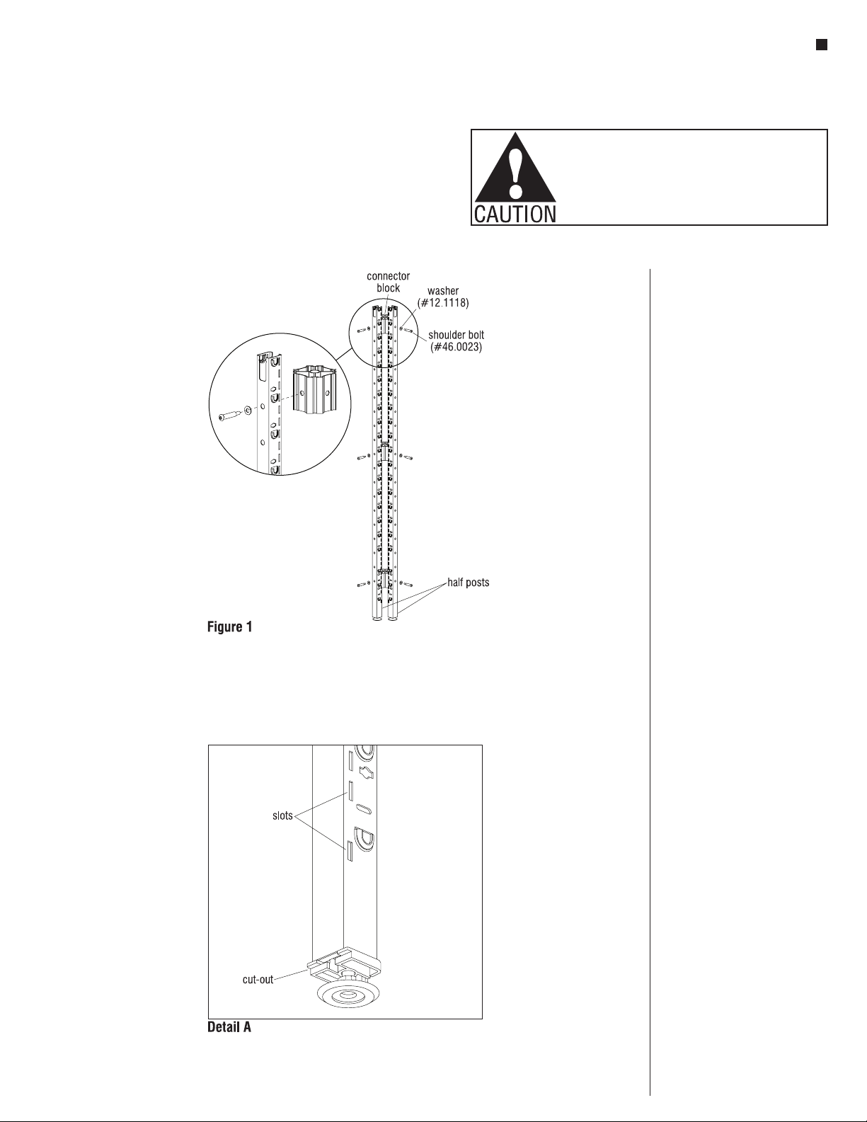
1. Assemble intersections by
bolting two, three, or four half
posts together using a connector
block, shoulder bolts and
washers with a 3/16” allen wrench
(Figure 1). Refer to page 7 for
the correct number of connector
blocks per intersection.
Note: The plastic inserts at
the bottom of the vertical posts
must be oriented such that the
recessed cut out is positioned
under the slots (Detail A).
Note: All half posts get one
connector block in the lowest
hole and one connector block in
the highest hole, with taller posts
requiring additional connectors.
See Planning Guide for more
detailed information. Position
connector blocks at heights that
avoid obstructing power and data
cabling. Refer to the
space-planning layout for power
and data locations.
6
WireWorks®Panel System
Assembly Instructions
Assemble units as described herein only. To do otherwise
may result in instability. All screws, nuts and bolts must be
tightened securely and must be checked periodically after
assembly. Failure to assemble properly, or to secure parts
may result in assembly failure and personal injury.
Assembling Intersections
(continued)
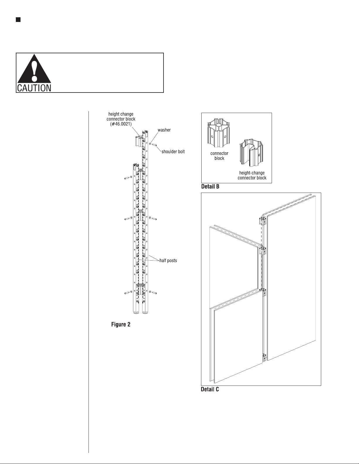
2. Install height-change connector
block (if required) to the frame
using, shoulder bolts and
washers with a 3/16” allen wrench
(Figure 2). Refer to the table on
next page for the correct number
of connector blocks.
Note: Height-change connector
blocks have a wire management
channel that allows cables
to be routed between two different
height panels (Detail B).
Note: Face the opening of all
height-change connector blocks
toward the shortest panel to
allow for lay-in wire management
(Detail C).
WireWorks® Panel System
Assembly Instructions
Assemble units as described herein only. To do otherwise
may result in instability. All screws, nuts and bolts must be
tightened securely and must be checked periodically after
assembly. Failure to assemble properly, or to secure parts
may result in assembly failure and personal injury.
7
Rules for Building
Intersections
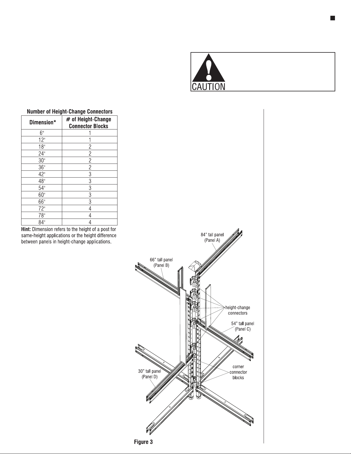
1. Determine quantity of connector
blocks by referring to
Number of Height-Change
Connectors chart.
2. Determine quantity of connector
blocks by identifying the shortest
panel in your intersection. Refer
to corresponding chart.
3. Determine quantity of
height-change connector blocks
by subtracting heights of the
two shortest panels. Refer to the
chart for order quantity. If your
intersection includes more than
two different heights, repeat this
process for all heights.
Hint: Start with shortest panel.
Use height difference between
shortest and next tallest, etc.
Sample
You Need (Refer to Figure 3)
Shortest panel
30” = 2 connector blocks
Second shortest panel
54”-30” = 24” or 2 height-change
connectors
Third shortest panel
66”-54” = 12” or 1 height-change
connectors
Tallest panel
84”-66” = 18” or 2 height-change
connectors
Total
2 connector blocks
5 height-change connector blocks

8
WireWorks®Panel System
Assembly Instructions
Assemble units as described herein only. To do otherwise
may result in instability. All screws, nuts and bolts must be
tightened securely and must be checked periodically after
assembly. Failure to assemble properly, or to secure parts
may result in assembly failure and personal injury.
Attaching Horizontals To
Verticals
Horizontals are used at the top
and bottom of a panel to space
the vertical posts apart the
appropriate distance for the panel
width you are building. One rail is
used at the top of the panel with
the opening facing upward and
one rail is used at the bottom
facing downward. Panels that
are made up of more than one
tile also use horizontals at
intermediate heights (with the
opening facing up).
Note: Refer to the
space-planning layout and start
with a panel corner intersection,
building out in two directions so
the panel frame is able to stand
on its own.
1. Slide a horizontal into the top of
a vertical half post with the rivets
above the pocket on the post.
Making sure all four rivets are
lined up with the corresponding
embosses, tap the horizontal into
place with a dead-blow style
mallet (Figure 4)
2. Referring again to the
space-planning layout, position
the appropriate vertical post
(full or half post) relative to
the horizontals and tap the
horizontals into place (Figure 5).
3. Repeat the above instructions,
building out in a direction
perpendicular to the first
horizontals from the corner post.
When this step is completed you
should have a partially assembled
90° corner that can support itself
(Figure 6).
Otros manuales para WireWorks
5
Tabla de contenidos
Otros manuales de Equipos de oficina de KI

KI
KI All Terrain Wall Rail Manual de usuario

KI
KI Backbone Media Platform Manual de usuario

KI
KI Likha Casegoods Manual de usuario

KI
KI 810 Manual de usuario

KI
KI WireWorks Manual de usuario

KI
KI Tattoo Flex Screen Manual de usuario

KI
KI Pull Out Worksurface Storage Manual de usuario

KI
KI WireWorks Manual de usuario

KI
KI WireWorks Manual de usuario

KI
KI WireWorks Manual de usuario


