
KFE KF-CMG-36 Manual de usuario

1
INSTALLATION & OPERATION MANUAL
CHEESE MELTER
Model: KF-CMG-36
WARNING: IMPROPER INSTALLATION, ADJUSTMENT, ALTERATION, SERVICE, MAINTENANCE
CAN CAUSE PROPERTY DAMAGE, INJURY OR DEATH. READ THE INSTALLATION, OPERATING AND
MAINTENANCE INSTRUCTIONS THOROUGHLY BEFORE INSTALLING OR SERVICING THIS EQUIPMENT.
Please call the Service Department and ask for contact information for your local service company.
2
IMPORTANT FOR YOUR SAFETY
THIS MANUAL HAS BEEN PREPARED FOR PERSONNEL QUALIFIED TO INSTALL GAS EQUIPMENT, WHO
SHOULD PERFORM THE INITIAL FIELD START-UP AND ADJUSTMENTS OF THE EQUIPMENT COVERED BY
THIS MANUAL.
POST IN A PROMINENT LOCATION THE INSTRUCTIONS TO BE FOLLOWED IN THE EVENT THE SMELL OF
GAS IS DETECTED. THISI NFORMATION CAN BE OBTAINED FROM THE LOCAL GAS SUPPLIER.
IMPORTANT
IN THE EVENT A GAS ODOR IS DETECTED, SHUT DOWN
UNITS AT MAIN SHUT OFF VALVE AND CONTACT THE
LOCAL GAS COMPANY OR GAS SUPPLIER FOR SERVICE.
FOR YOUR SAFETY
DO NOT STORE OR USE GASOLINE OR OTHER
FLAMMABLE VAPORS OR LIQUIDS IN THE VICINITY OF
THIS OR ANY OTHER APPLIANCE.
WARNING: IMPROPER INSTALLATION,
ADJUSTMENT, ALTERATION, SERVICE OR MAIN-
TENANCE CAN CAUSE PROPERTY DAMAGE, INJURY OR
DEATH. READ THE INSTALLATION, OPERATING AND
MAINTENANCE INSTRUCTIONS THOROUGHLY BEFORE
INSTALLING OR SERVICING THIS EQUIPMENT.

3
INSTALLATION, OPERATION AND CARE OF
CHEESE MELTER
GENERAL
Cheese melter are produced with quality workmanship and materials. Proper installation, usage, and
maintenance of your Cheese melter will result in many years of satisfactory performance.
It is suggested that you thoroughly read this entire manual and carefully follow al l of the
instructions provided.
Product parameter:
Model
BTU
Orifice size
Regulator pressure
Nat.
LP
Nat.
LP
36”Cheese melter
33,500
#31
#52
5”WC
10”WC
THIS APPLIANCE IS EQUIPPED FOR NATURAL GAS.
For Natural gas when equipped with No. #31 drill size orifice.
For LP gas when equipped with No.#52 drill size orifice.
For conversion to LP gas orifice see instruction plate on the appliance, see Page 11.
INSTALLATION
Before installing, verify that the type of gas supply (natural or propane) agrees with the
specifications on the rating plate located underneath the Cheese melter rack drip tray. If the
supply and equipment requirements do not agree, do not proceed with the installation. Contact
your dealer immediately.
UNPACKING
Immediately after unpacking, check for possible shipping damage. If the Cheese melter is found to be
damaged, save the packaging material and contact the carrier within 15 days of delivery.
Before installing, verify that the type of gas (natural or propane) and the clearance dimensions (see below)
agree with the specifications on the rating plate which is located under the crumb tray on the right side.
LOCATION
The equipment area must be kept free and clear of combustible substances.
Minimum Clearance
Combustible Construction
Non-Combustible Construction
Rear
2”
0”
Sides
2”
0”
Bottom
0”
0”

4
The installation location must allow adequate clearances for servicing and proper operation.
A minimum front clearance of 24" is required.
Do not obstruct the flow of combustion and ventilation air. Adequate clearance for air openings into the
combustion chamber must be provided. Make sure there is an adequate supply of air in the room to replace air
taken out by the ventilating system. Do not permit fans to blow directly at the Cheese melter. Avoid wall-type fans
which create air cross currents with in the room. Avoid open windows next to the Cheese melter. Maintain an 18"
(46 cm) clearance from the top of the Cheese melter flue vent to the filters of the hood venting system.
INSTALLATION CODES AND STANDARDS
The Cheese melter must be installed in accordance with:
In the United States of America:
1. State and local codes.
2. National Fuel Gas Code, ANSI-Z223.1/NFPA #54 (latest edition). This shall include but not be limited to: NFPA #54
Section 10.3.5.2 for Venting. Copies may be obtained from The American Gas Association Accredited Standards
Committee Z223, @ 400N. Capita l St. NW, Washing ton, DC 20001 or the Secretary Standards Council, NFP A,1
Batterymarch Park Quincy, MA 02169 -7471
NOTE: In the Commonwealth of Massachusetts
Al l gas appliances vented through a ventilation hood or exhaust system equipped with a damper or with a power means
of exhaust shall comply with 248 CMR.
3.NFPA Standard # 96 Vapor Removal from Cooking Equipment , latest edition, available from the National Fire
Protection Association, Batterymarch Park , Quincy, MA 02269. In Canada:
1. Local codes.
2. CAN/CSA-B 149.1 Natural Gas Installation (latest edition)
3. CAN/CSA-B 149.2 Propane Installation Code (latest edition), available from the Canadian Gas Association, 178
Rexdale Blvd., Etobicoke, Ontario, Canada M9W 1R3
The appliance and its individual shutoff valve must be disconnected from the gas supply piping system during any
pressure testing of that system at test pressures in excess of 1/2ps i(3.5kPa).
The appliance must be isolated from the gas supply piping system by closing its individual pressures equal to or less than
1/2 psi (3.5 kPa).
GAS CONNECTIONS
Codes require that a gas shutoff valve be installed in the gas line ahead of the Cheese melter.
NATURAL GAS: Standard orifices are set at 5" W .C. (Water Column). A pressure regulator is supplied and must be
installed when the Cheese melter is connected to the gas supply.
LP GAS: Standard orifices are set at 10" W .C. (Water Column). A pressure regulator is supplied and must be installed
when the Cheese melter is connected to the gas supply.
5
The gas supply line must be ¾” or larger. If flexible or semi-rigid connections are used, the inside diameter must
be the equivalent of ¾” iron pip e or larger. All connections of the flexible and semi-rigid type must comply with
all local and national requirements. Make sure gas piping is clean and free of dirt, piping compound, and
obstructions.
WARNING: PRIOR TO LIGHTING, CHECK ALL JOINTS IN THE GAS SUPPLY LINE FOR LEAKS. USE SOAP AND WATER
SOLUTION. DO NOT USE AN OPEN FLAME.
After piping has been checked for leaks, all piping receiving gas should be fully purged to remove air.
GAS PRESSURE REGULATOR INSTALLATION
Gas regulator pressure is preset at 5” Water Column (W .C.) for natural gas, and 10” W .C.
For propane gas. Minor adjustments may be required based on site specific gas pressure.
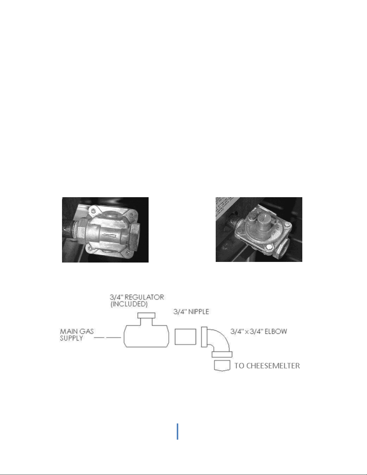
Install the regulator as close to the Cheese melter on the gas supply line as possible. Make sure that the arrow on
the underside of the regulator is oriented in the direction of gas flow to the Cheese melter (Fig. 1) and the
regulator is positioned with the vent plug and adjustment screw upright ( Fig. 2). A recommended plumbing
schematic is listed below only for Cheese melter units as a guide to the installer and it is in no way liable for
plumbing installation ( Fig. 3).
Fig.1 Fig.2
Fig.3
6
The minimum supply pressure (upstream of the regulator) should be 7-9” W .C. for natural gas and 11 -12” W .C.
for propane gas. At no time should the regulator be connected to supply pressure greater than ½ psi (3.5 k Pa) or
14” W .C.
FLUE CONNECTIONS
DO NOT obstruct the flow of flue gases from the flue located on the rear of the Cheese melter. It is
recommended that the flue gases be ventilated to the outside of the building through a ventilation system
installed by qualified personnel.
Information on the construction and installation of ventilating hoods may be obtained from the standard f or
"Vapor Removal from Cooking Equipment," NFPA No. 96 (latest edit ion), available from the National Fire
Protection Association, Batterymarch Park, Quincy, MA02269.
WALL MOUNTING OF CHEESE MELTER
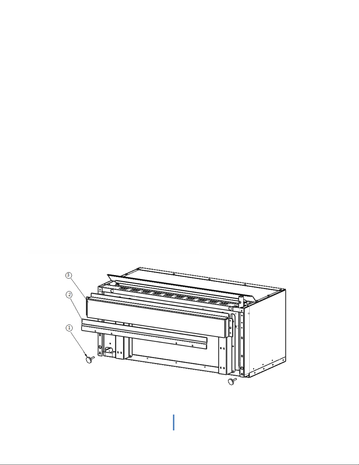
For Cheese melter to be mounted on a Wall (Fig.4).
The separate wall mounting bracket accessory will be needed to wall mount the unit.
1. Place mounting bracket (balloon 3) and screws provided.
2. Place leveling Screws (balloon 1) into Cheese melter.
3. Place wall bracket (balloon 2) on the wall were you want the Cheese melter.
(Proper anchoring needed at least 50 Ibs. support per anchor)
4. Lower Cheese melter into wall bracket
5. Adjust leveling screws to level Cheese melter and bring parallel to wall. CHEESE MELTER MUST BE LEVEL TO
OPERATE PROPERLY.
Fig. 4
7
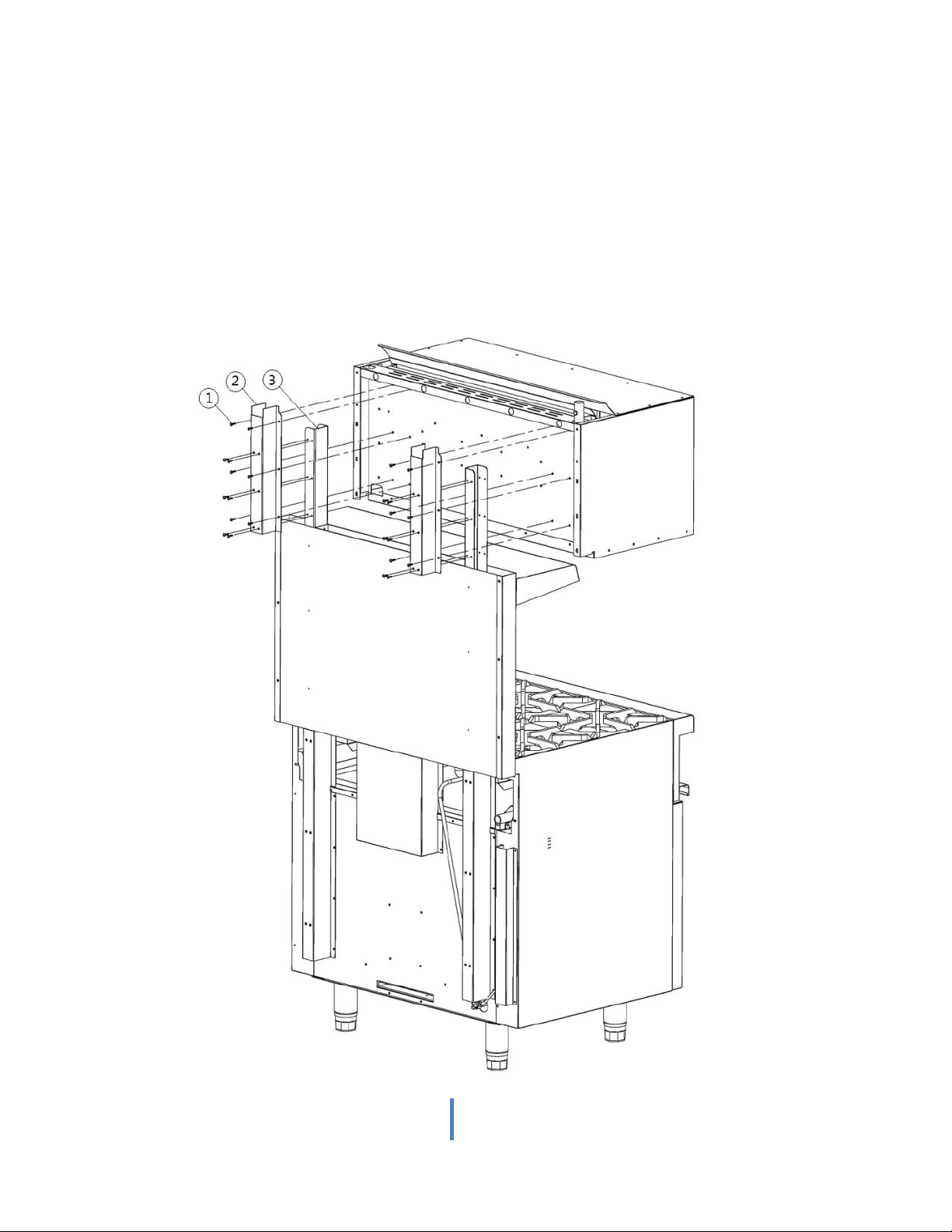
MOUNTING OVER GAS RANGE BACK
DESIGNED TO MOUNT THIS CHEESE MELTER CHEESE MELTER (Fig. 6)
If the Cheese melter is to be mounted over a gas range WHICH IS DESIGNED SPECIFICALLY TO RECEIVE THIS
KFECHEESE MELTER, it must be installed according to the instructions below:
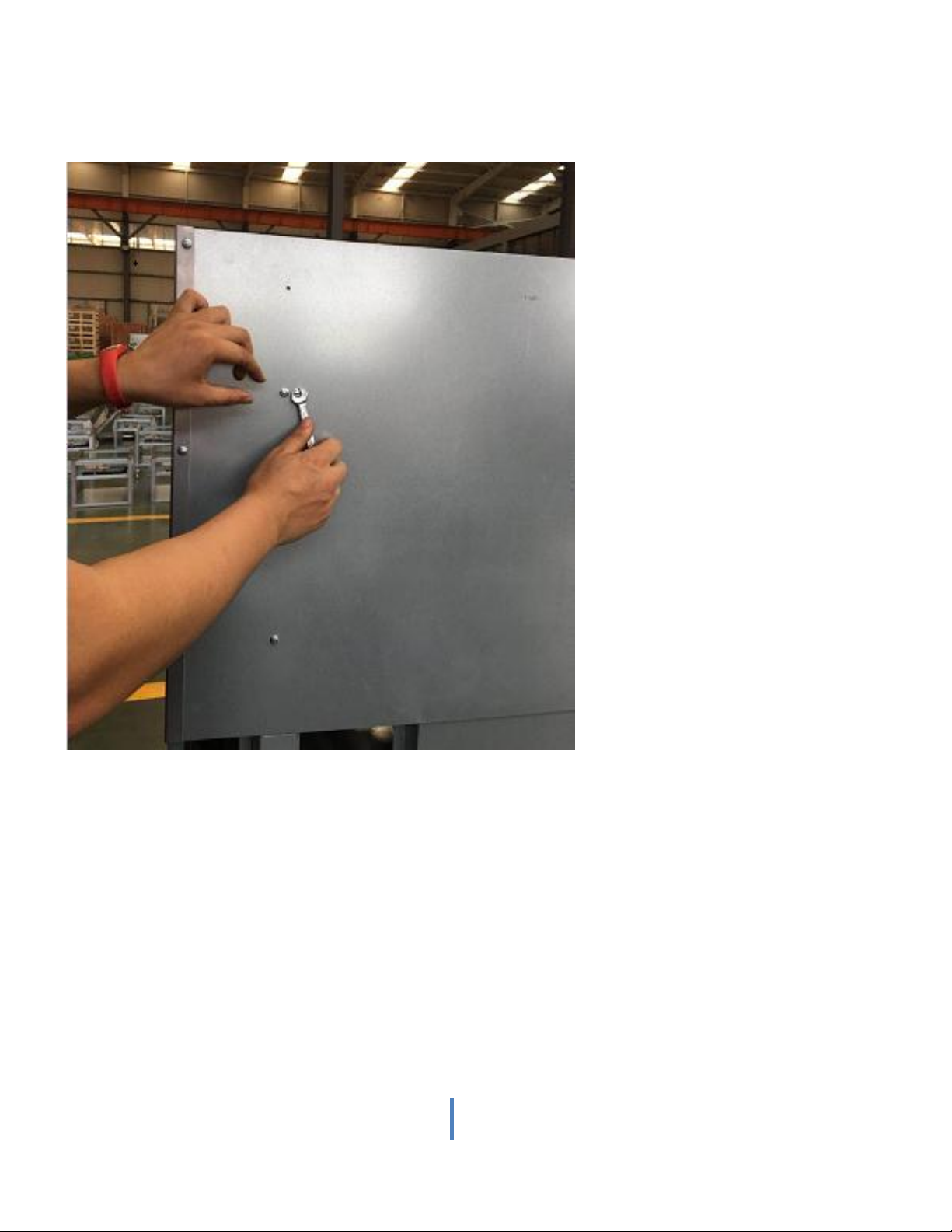
Using the twelve bolts provided (balloon 1), install mounting brackets (balloon 2) on both top mounting posts
(balloon 3). See photos below to show how to install posts on range back.
Fig. 6
8
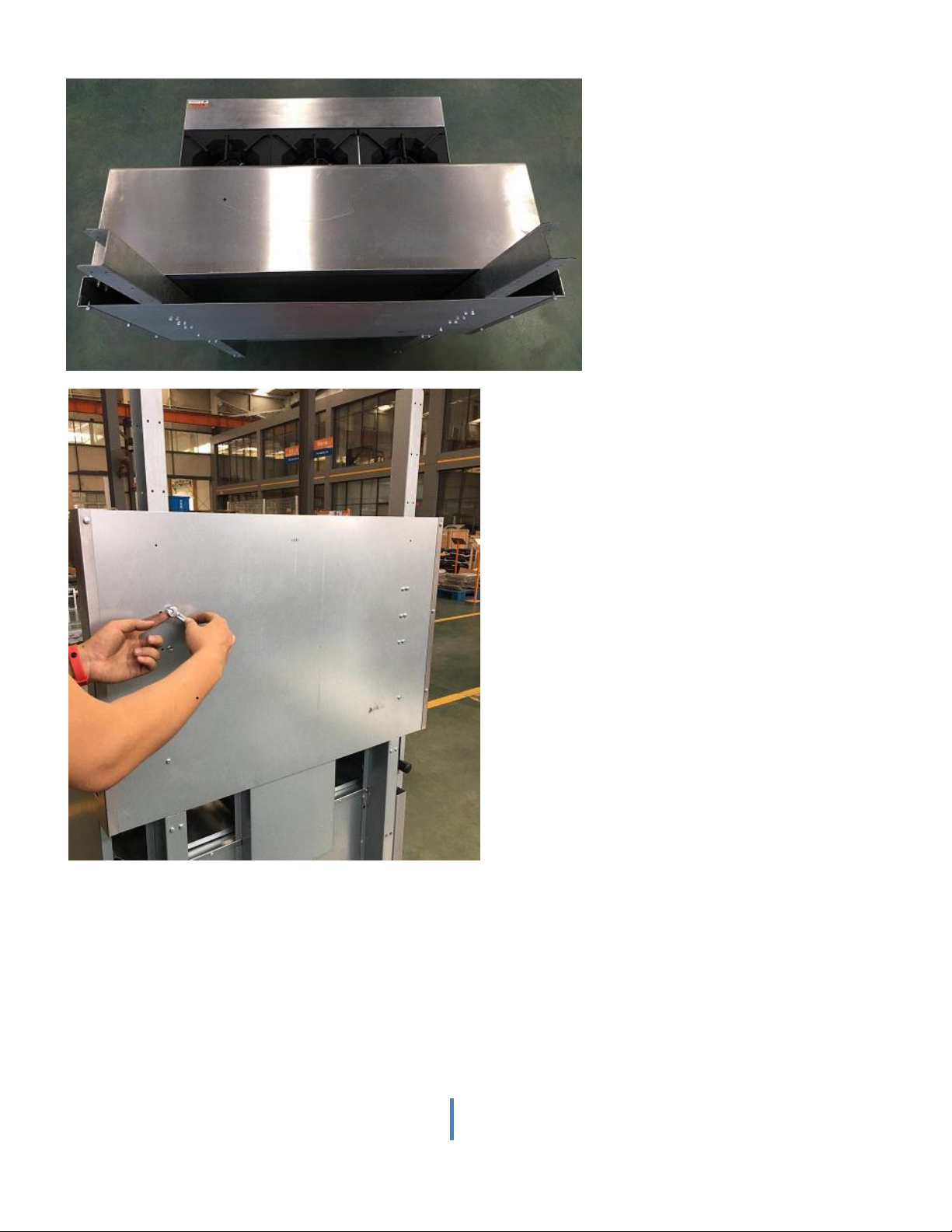
Cheese melter - Range back installation
1. Take off the 12 self-tapping screws on the range back.
2. Insert the Cheese melter support column into the Range back plate as shown and tighten it with screws
9
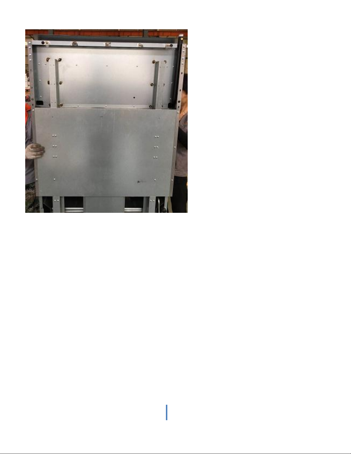
3. Lift Cheese melter and attach it to the proper position of the support column
10
4. Take two brackets out of the package
Tabla de contenidos


