Kewtech EVSE Manual de usuario

EVSE Adapter
Manual
Manual
KT810

2
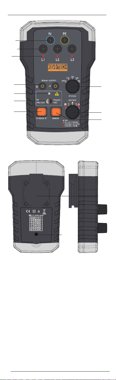
Operation Elements And Connectors
1. Measuring terminals N, PE
2. Measuring terminals L1, L2, L3
3. Phase indicators LED for L1, L2, L3 terminals
4. PE and CP Signal output terminals
5. PE Pre-Test warning light indicator
6. PE Pre-Test touch probe
7. “E” - CP Error simulation button
8. PP (Proximity Pilot) State rotary switch selector
(open, 13A, 20A, 32A and 63A)
9. CP (Control Pilot) State rotary switch selector (A, B, C, D)
10. PE Error (Earth Fault) simultion button
11. Mains socket. Use for test purpose only.
Allowed current max. 10 A
12. Mains socket fuse compartment.
Adapter is equipped with 25 Cm cable with type 2 EVSE connector.
KT810
➊
➋
➌
➍
➎
➏
➐
➑
➒
➓
➊ ➊
➊ ➋

Content
ENGLSIH
3
Content
Operation Elements And Connectors......................................2
Refarences..........................................................................4
Safety Refarences................................................................4
Testing ...............................................................................5
PE Pre-Test................................................................5
Test procedure ..........................................................5
Proximity Pilot (PP) State (Cable Simulation)..............5
Control Pilot (CP) State (Vehicle Simulation)...............6
CP Signal output terminals.........................................6
CP Error “E” simulation..............................................6
PE Error (Earth Fault) simulation................................6
Phase indicator..........................................................7
Mains socket ............................................................7
Measuring terminals L1, L2, L3, N and PE ..................7
Fuse repleacement ....................................................7
Cleaning ...................................................................7
Specifications.......................................................................8

References
4
References
References marked on instrument or in
instruction manual
Warning of a potential danger, follow with instruction
manual.
Reference! Please use utmost attention.
Caution! Dangerous voltage. Danger of electrical shock.
Ground terminal
Continuous double or reinforced insulation category II IEC
536 / DIN EN 61140.
Conformity symbol, the instrument complies with the valid
directives. It complies with the EMC Directive (2014/30/
EU), Standard EN 61326 is fulfilled. It also complies with
the Low Voltage Directive (2014/35/EU) Standards EN
61010-1 and EN 61010-031.
Instrument fulfils the standard (2012/19/EU) WEEE.
This marking indicates that this product should not be
disposed with other household wastes throughout the EU.
To prevent possible harm to the environment or human
health from uncontrolled waste disposal, recycle it re-
sponsibly to promote the sustainable reuse of material
resources. To return your used device, please use the re-
turn and collection systems or contact the retailer where
the product was purchased. They can take this product for
environmental safe recycling.
Safety References
The respective accident prevention regulations established
by the professional associations for electrical systems and
equipment must be strictly met at all times.
In order to avoid electrical shock, the valid safety and
VDE regulations regarding excessive contact voltages must
receive utmost attention, when working with voltages ex-
ceeding 120V (60V) DC or 50V (25V)rms AC. The values
in brackets are valid for limited ranges (as for example
medicine and agriculture).
Measurements in dangerous proximity of electrical sys-
tems are only to be carried out in compliance with the
instructions of a responsible electronics technician, and
never alone.
If the operator’s safety is no longer ensured, the instru-
ment is to be put out of service and protected against use.
The safety is no longer insured, if the instrument:
• shows obvious damage
• does not carry out the desired measurements
• has been stored for too long under unfavourable conditions
• has been subjected to mechanical stress during transport.
The instrument may only be used within the operating
ranges as specified in the technical data section.
Avoid any heating up of the instrument by direct sunlight
to ensure perfect functioning and long instrument life.

References Safety references / Testing
ENGLSIH
5
Cable current capability Resistance between PP and PE
No cable Open (∞)
13 A 1.5 kΩ
20 A 680Ω
32 A 220Ω
63 A 100Ω
References
The opening of the instrument for fuse replacement, for
example, may only be carried out by professionals. Prior to
opening, the instrument has to be switched off and discon-
nected from any current circuit.
The instrument may only be used under those conditions
and for those purposes for which it was conceived. For this
reason, in particular the safety references, the technical
data including environmental conditions and the usage in
dry environments must be followed.
When modifying or changing the instrument, the operational
safety is no longer ensured.
Testing of the charging station
PE Pre-Test
Prior all other tests PE pretest must be successfully car-
ried out. Never touch PE terminals at the mains socket
on the back side before PE pretest is sucessfully fin-
ished.
The PE Pre-Test allows the operator to test the PE conductor for
possible presence of dangerous voltage against earth.
Normaly the PE conductor is connected to earth and has no volt-
age against earth.
In the case when PE conductor is not connected to earth (mistakely
connected to phase or possibly broke) it can bring operator or
users in to the life hazard situation .
Test procedure:
- Connect the test adapter to the charging station
- Touch the probe (no. 6 on the picture) with a bare finger
- If light indicator (no. 6 on the picture) is illuminated then
dangerous voltage is present at PE conductor. Stop further
testing immediately and check for a possible wiring fault.
Do not wear gloves while performing this test and ensure a proper
connection to earth. Never touch any metal parts during this test.
In case of improper earthing (e.g., operators body isolated from
the earth) this test may be not reliable.
Proximity Pilot (PP) State (Cable Simulation)
With the PP State rotary switch, can be simulated current capa-
bilitie of the charging cable. Current capabilities are simulated
with different resistances connected between PP and PE conduc-
tors. Correlation between resistance and current capability of the
charging cable is shown in the table below.

Testing
6
Control Pilot (CP) State (Vehicle Simulation)
With the CP State rotary switch selector various vehicle states can
be simulated. Vehicle states are simulated with different resistanc-
es connected between CP and PE conductors. Correlation between
resistance and vehicle states is shown in Table below.
CP Signal output terminals
CP output terminals are short connected to the CP and PE conduc-
tors of the tested charging station via the test cable (no.4 on the
picture).
Use an oscilloscope to check the waveform and amplitude of the
CP signal.
Control Pilot function uses Pulse Width Modulation (PWM) to code
comunication between a vehicle and charging station. The duty
cycle of the PWM signal defines the possible available charging
current, while amplitude defines charger state.
For details of communication protocol please refer to IEC/EN
61851-1 and the documentation of the manufacturer of the
charging station.
Important note: In the case of wrong wiring of the
charging station, low signal CP test terminals can get
high, live hazard voltage.
CP Error “E” simulation
“E” - CP Error simulation button (no. 7 on the picture). With
pushed button “E” operator can simulate behaviour of the staion
when there is established a short circuit between CP and PE
through internal diode (acc. to standard IEC/EN 61851-1). In the
case of CP Error (“E” is pushed), result should be aborting of the
charging process and new charging process is prevented.
PE Error (Earth Fault) simulation
With the PE Error button (no. 10 on the picture), interruption of
the PE conductor is simulated. As a result the pending charging
process is aborted and new charging process is prevented.
Vehicle State State Description CP-PE Resistance CP terminal voltage
A Electric vehicle Open (∞) ±12V @ 1KHz
not connected
B Vehicle connected, 2.74K +9V/-12V @ 1KHz
not ready to charge
Electric vehicle connected, 882Ω +6V/-12V @ 1KHz
C ready to charge,
ventilation not required
Electric vehicle connected, 246Ω +3V/-12V @ 1KHz
D rady to charge,
ventilation required

Testing
ENGLSIH
7
Phase indicator
The phase indicators are LEDs, one LED for each phase (no. 3 on
the picture). When the test adapter is connected to the charging
station and phase voltages are present at the charging connector,
the LED indicators will illuminate.
• In the case neutral (N) conductor is not present or it is in-
terrupted, LED indicators will not indicate possible voltage
presence at L1, L2 and L3 conductors. The LED indicators
are not intendet to be used for phase sequence testing.
• When tested single phase charging station, only one LED
will illuminate.
Mains socket
The mains socket (no. 11 on the picture) is connected to L1, N and
PE conductors of the charging station. External load can be con-
nected to the socket. This output is intended for measuring purpos-
es only and offers the possibility to check the electric power meter
functionality. It is not allowed to supply anything else trough the
socket. The max. current is limited to 10 A with an T10A/250V,
5×20 mm fuse located in the back compartment of the Adapter.
Measuring terminals L1, L2, L3, N and PE
Measuring terminals (no. 1 and 2 on the picture) are directly con-
nected to L1, L2, L3, N and PE conductors of the tested charging
station. It is alowed to use these for measuring purposes only.
It is not allowed to draw current over a longer period or supply
anything else. An appropriate measurement instrument is needed.
Fuse repleacement
Prior to fuse replacement, ensure that multimeter is dis-
connected from external voltage supply and the other connected
instruments (such as UUT, control instruments, etc.)
Only use fuses as described in the technical data section!
Using auxiliary fuses, in particular short-circuiting fuse holders is
prohibited and can cause instrument destruction or serious bodily
injury of operator.
The fuse (T 10 A / 250 V, 5 x 20 mm). If no voltage is present
between the L and N terminals of mains socket when the charging
connector is connected to the charging station and the charging
station is in charging mode, it is possible that mains socket fuse
is broken.
• In that case disconnect adapter from the charging staion
• open cover from the back of the adapter (apropriate screw-
driver is necessary)
• Locate and repleace fuse with the fuse of the same type.
• Return back cover of the fuse compartment.
Cleaning
If the instrument is dirty after daily usage, it is advised to clean
it by using a humid cloth and a mild household detergent. Prior
to cleaning, ensure that instrument is switched off and discon-
nected from external voltage supply and any other instruments
connected (such as UUT, control instruments, etc.).
Never use acid detergents or dissolvent for cleaning.

Specifications
8
Specifications
Input voltage: max. 250V (single phase), max. 430V
(three phase) 50/60Hz
Measurement Category: CAT II 300V
Mains socket rating: 250V/10A
Mains socket protection: Fuse T10A/250V
PP simulation: Open circuit, 13A, 20A, 32A, 63A
CP simulation: States A, B, C, D
Error simulation: CP error “E”, PE (earth fault) error
PE Pre-Test: Yes
Test connector type: IEC62196-2 Type 2 male
Test cable length: 25 Cm
Working temperature: 0 … +40ºC
Storage temperature: -10 … +50ºC
Humidity: 0-80% RH
Exclusive importer for France:
TURBOTRONIC s.a.r.l.
Z.I. les Sables
4, avenue Descartes – B.P. 20091
91423 Morangis Cedex · FRANCE
T: 01.60.11.42.12 · F: 01.60.11.17.78
Exclusive importer for Belgium:
C.C.I. SA
Louiza-Marialei 8, b. 5
2018 Antwerpen · BELGIQUE
T: 03/232.79.64 · F: 03/231.98.24
E-mail: info@ccinv.be · www.ccinv.be

Adaptateur EVSE
Manuel d‘utilisation
Manuel
KT810

2
Éléments d’utilisation et connexions
KT810
➊
➋
➌
➍
➎
➏
➐
➑
➒
➓
➊ ➊
➊ ➋
1. Bornes de mesures N, PE
2. Bornes de mesures L1, L2, L3
3. Indicateurs de phases LED pour les bornes L1, L2 et L3
4. Bornes de signaux de sorties PE et CP
5. Indicateur voyant d’avertissement PE Pré-test
6. Sonde tactile PE Pré-test
7. Bouton de simulation “E” –CP
8. PP (Proximity Pilot) Bouton rotatif (open, 13A, 20A, 32A
et 63A)
9. CP (Control Pilot) Bouton rotatif (A,B,C,D)
10. Erreur PE (Erreur de terre) bouton de simulation
11. Prise principale. A utiliser seulement pour effectuer des tests.
Courant maximum toléré 10A
12. Boitier fusible réseau
L’adaptateur est muni d’un câble de 25cm à connecteur EVSE de
Type 2
Tabla de contenidos
Idiomas:
Otros manuales de Adaptador de Kewtech