4
Kentech Instruments Ltd., Unit 9, Hall Farm Workshops, South Moreton, Didcot, Oxon, OX11 9AG, U.K.
10th. July 1999
1 INTRODUCTION
Thismanualdescribestheoperationanduseofthespecialpulsechoppingsystem.Thishasbeendesignedtochop
the back end of a laser pulse at rates to 20kHz.
1.1 SPECIFICATIONS
Pulse output voltage range -220 to -470 volts into 50 Ω.
Maximum repetition rate ~20kHz
Trigger input >2 volts 10ns f.w.h.m. into 50Ω.
Jitter Less than 50ps
Trigger delay 50ns to end of supplied cables (approx. 35ns plus 15ns in the cables)
Power input Universal
85 to 264 volts A.C. at 47 to 440Hz.
2 amp fuse, type T (anti-surge)
This unit contains an auto-resetting thermal trip rated at 70°C
Maximum average power consumption 60 watts.
Connectors
Power IEC
Trigger input BNC
Outputs SMA
2 GETTING TO KNOW THE INSTRUMENT
The pulser consists of a trigger circuit, a variable voltage power supply and four pulsers. The trigger circuit
processes the incoming trigger signal, and provides outputs to the four pulsers with provision for a small amount of
individual delay adjustment. It also provides trigger pulses for the LED flashing (triggered light).
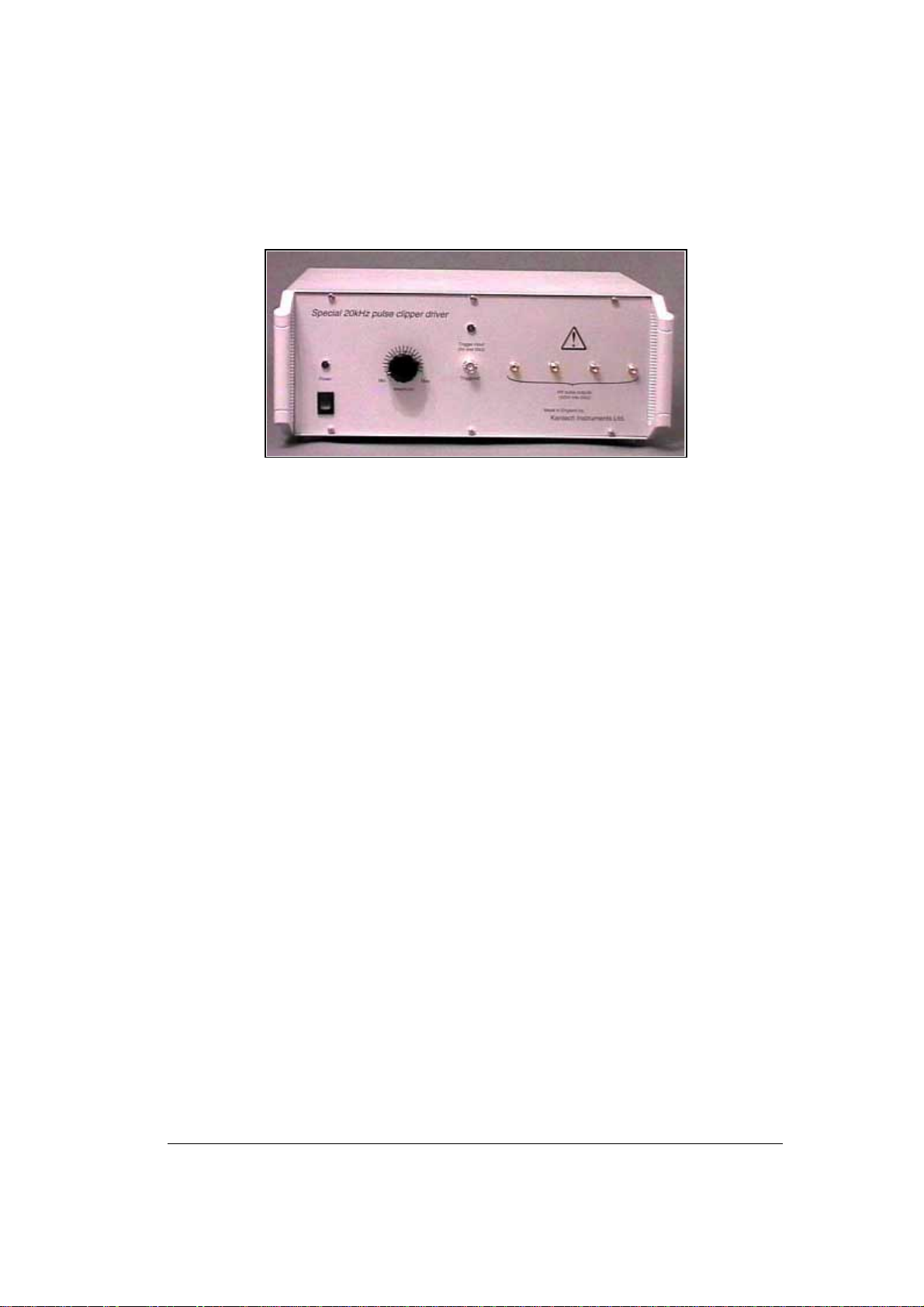
2.1 FRONT PANEL CONTROLS, CONNECTIONS AND INDICATORS.
The front panel is shown in figure 1.
The “Amplitude” control controls the pulse voltage in approximately 20 volt steps from 210 volts to 470 volts.
All four channels are adjusted together. This is effectively the voltage into a 50Ωload. By mismatching the end of the
cable to the load up to twice this voltage is available.
The pulser is not reverse terminated. Consequently a pulse reflected from the load will also be reflected from the
pulser and arrive at the load again. The reflection arrives at the loads at a time equal to the round trip time of the cables.
Several reflections occur.
There are five front panel connectors. The trigger input and the four main outputs. Note that the main outputs
contain a DC path to ground and so if it is necessary to bias the load with a DC signal the pulser must be disconnected.
2.2 REAR PANEL CONNECTIONS
Thepowerinletis ontherearpanel.Thepowerinlet isfilteredandwillacceptIECleads. Itusesauniversalsupply
that will run from a variety of AC voltages, see specification.
3 USE
The unit is intended to pulse a small capacitive load for 30ns at repetition rates up to 20kHz. In particular for
pulsing a pair of pockels cells using 25 ohm feed to each to keep the RC risetime good.
3.1 CONNECTIONS AND APPLICATIONS
The pulser is designed for use with Pockels cells between polarisers and consequently the pulse amplitude can
be varied to adjust the operating point. The greatest contrast will be achieved when the pulse amplitude at the cells