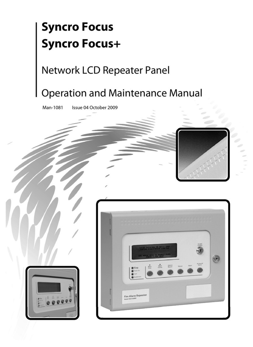
Kentec Electronics Sigma XT+ Manual de usuario

Sigma XT+
Extinguishant Control Panel
User Manual
Man-1134 Issue 02 June 2013
*Man-1134*

Man-1134 Sigma XT+_ECP_02 Page 2 of 5
Index
Panel operation – Access levels 1 and 2............................................................................... 3
1 Normal condition.................................................................................................................................. 3
2 Access level 2...................................................................................................................................... 3
2.1 Disable Extinguishant release outputs. ................................................................................................. 3
2.2 Disable Manual release....................................................................................................................... 3
2.3 Disable Stage 1 output....................................................................................................................... 3
2.4 Disable Stage 2 output....................................................................................................................... 3
2.5 Disable Released output..................................................................................................................... 3
2.6 Disable Extract output........................................................................................................................ 4
2.7 Turn on Extract output....................................................................................................................... 4
2.8 Reset............................................................................................................................................... 4
2.9 Sounder fault.................................................................................................................................... 4
2.10 Power fault..................................................................................................................................... 4
2.11 System fault................................................................................................................................... 4
2.12 Lamp test....................................................................................................................................... 4
2.13 Hold condition................................................................................................................................. 4
2.14 Turn on Extract output ..................................................................................................................... 4
2.15 Released condition........................................................................................................................... 4
2.16 Low pressure switch......................................................................................................................... 4
2.17 Manual only mode ........................................................................................................................... 5
2.18 Manual Release ............................................................................................................................... 5
2.19 Abort input..................................................................................................................................... 5

Man-1134 Sigma XT+_ECP_02 Page 3 of 5
Panel operation – Access levels 1 and 2
1 Normal condition
Under normal conditions and in Manual & Auto mode, the unit will have only the green, Power On LED lit. With the ENABLE
controls key switch off, LCD will show:
Manual & Auto
When switched to Manual Only mode, the Manual only yellow LED will be lit and the display will show:
MANUAL MODE
The ECU has 3 access levels. Access level 1 is available at all times and allows operation the Buzzer silence button and the Lamp
test function by holding down the EXIT button for more than 2 seconds. Access level 2 is enabled after operation of the front
panel mounted Enable Controls key switch and Access level 3 allows configuration options to be set following operation of the
Write Enable switch while at access level 2 (Enable Controls keyswitch operated).
2 Access level 2
With the Enable Control key switch operated, the LCD will display:
Access level 2 ►
ENTER for Menu
Press the ENTER button to view the following menu options.
2.1 Disable Extinguishant release outputs.
To disable both of the Extinguishant release outputs, press the UP button on the module while at access level 2.
The display will show:
DISABLE
EXTING. RELEASE ? Press the Enter button to select this function. The display will show:
ENABLE
EXTING. RELEASE ? The yellow disabled LED on the module that has been disabled will be lit.
Turn the Enable key switch off to leave the disablement active. To re-enable the Extinguishant outputs repeat the procedure
above.
2.2 Disable Manual release
To disable all Manual release inputs (front panel mounted and remotely connected), press the UP button on the module while at
access level 2 until the module displays:
DISABLE
MANUAL RELEASE ? Press the Enter button to select this function. The display will show:
ENABLE
MANUAL RELEASE ? The yellow disabled LED on the module that has been disabled will be lit.
Turn the Enable key switch off to leave the disablement active. To re-enable the manual release facility repeat the procedure
above.
2.3 Disable Stage 1 output
To disable the 1st Stage relay output, press the UP button on the module while at access level 2 until the display shows:
DISABLE
stage 1 output ? Press the Enter button to select this function. The display will show:
ENABLE
STAGE 1 OUTPUT ? The yellow disabled LED on the module that has been disabled will be lit.
Turn the Enable keyswitch off to leave the disablement active. To re-enable the Stage 1 relay output repeat the procedure
above.
2.4 Disable Stage 2 output
To disable the 2nd Stage relay output, press the UP button on the module while at access level 2 until the display shows:
DISABLE
stage 2 output ? Press the Enter button to select this function. The display will show:
ENABLE
STAGE 2 OUTPUT ? The yellow disabled LED on the module that has been disabled will be lit.
Turn the Enable keyswitch off to leave the disablement active. To re-enable the Stage 2 relay output repeat the procedure
above.
2.5 Disable Released output
To disable the Released relay output, press the UP button on the module while at access level 2 until the display shows:
DISABLE
released output ? Press the Enter button to select this function. The display will show:
ENABLE
released OUTPUT ? The yellow disabled LED on the module that has been disabled will be lit.
Turn the Enable keyswitch off to leave the disablement active. To re-enable the Released relay output repeat the procedure
above.

Man-1134 Sigma XT+_ECP_02 Page 4 of 5
2.6 Disable Extract output
To disable Extract relay output, press the UP button on the module while at access level 2 until the display shows:
DISABLE
extract output ? Press the Enter button to select this function. The display will show:
ENABLE
extract OUTPUT ? The yellow disabled LED on the module that has been disabled will be lit.
Turn the Enable keyswitch off to leave the disablement active. To re-enable the Extract relay output repeat the procedure above.
2.7 Turn on Extract output
To turn on the extract relay output, press the DOWN button on the module while at access level 2 until the display shows:
TURN ON
EXTRACT OUTPUT Press the Enter button to select this function. The display will show:
TURN OFF
EXTraCT OUTPUT ? The yellow disabled LED on the module that has been disabled will be lit.
Turn the Enable keyswitch off to leave the Extract output active. To turn off the Extract output, repeat the procedure above.
Note: the extract output does not turn off when the module is reset.
2.8 Reset
To reset the ECU, insert the Enable key, turn to the right then press the Reset button.
The unit will reset only after the Reset Inhibit timer has expired once the activated condition has been established.
2.9 Sounder fault
A fault on either of the sounder circuits will light the Fault LED and the ECU will display:
stage 1 alarms
fault
or
stage 2 alarms
fault
2.10 Power fault
Failure of the mains power or disconnection of the standby battery will cause the Fault LED to light and the display will show:
POWER SUPPLY
FAULT
2.11 System fault
The System Fault and general fault LEDs will light if the configuration memory has not been set or has become corrupted
2.12 Lamp test
Indicators can be lamp tested by holding down the EXIT button for more than 2 seconds.
2.13 Hold condition
Activation of the Hold input on the ECU or at a remotely mounted status unit will cause the Hold Activated indicator to light on
the ECU and on any status units or ancillary boards connected to it.
If the ECU is in the Activated condition and the pre-release timer is running then the Extinguishant release sequence will be
halted and the pulsing, 2nd stage sounders shall change to 1 second on, 2 seconds off.
Release of the Hold input shall re-start the pre-release timer from maximum.
2.14 Turn on Extract output
To turn on the extract relay output, press the DOWN button on the module while at access level 2 until the display shows:
TURN ON
EXTRACT OUTPUT Press the Enter button to select this function. The display will show:
TURN OFF
EXTRACT OUTPUT ? The yellow disabled LED on the module that has been disabled will be lit.
Turn the Enable key switch off to leave the Extract output active. To turn off the Extract output, repeat the procedure above.
Note:theextractoutputdoesnotturnoffwhenthemoduleisreset.
2.15 Released condition
The released pressure switch input will be connected to a pressure switch mounted on the Extinguishant cylinder which operates
when the Extinguishant has been released. This will activate the released indicator on the ECU.
If the Extinguishant has been released by mechanical means i.e. the ECU is not in the activated condition, operation of the
released pressure switch input will establish the Released condition.
2.16 Low pressure switch
The low pressure switch input will be connected to a pressure switch on the Extinguishant cylinder which will operate if the
pressure in the cylinder falls below a set point. This will happen after the Extinguishant has been released but may happen
before release through a leak. The fault LED on the ECU and on the detection part will light and the buzzer will sound when this
input is operated.

Man-1134 Sigma XT+_ECP_02 Page 5 of 5
2.17 Manual only mode
The mode of the system can be toggled between Manual Only and Automatic & Manual by operating the Mode select key switch.
When the ECU is in Manual Only mode, the Extinguishant cannot be released via a serial connection to a Sigma CP fire control
panel or operation of the monitored activation inputs.
The mode can also be changed to manual by the external mode select input or a keyswitch on a status unit. Any mode select
input that is switched to Manual only mode will override a keyswitch switched to Automatic and Manual mode. All inputs must be
switched to Manual and Automatic mode for the ECU to be in Automatic and Manual mode.
2.18 Manual Release
The ECU may be activated by Manual release inputs via the manual release control on the front panel, a remotely mounted
Manual release control connected to the monitored manual release inputs or by a manual release control mounted on a status
unit.
Operation of any of these Manual release controls will immediately activate the ECU and begin the pre-release timer (if the
module is configured to have a time delay for Manual release inputs).
2.19 Abort input
The ECU has the facility for connection of an Abort control. Operation of the Abort input during the pre-release delay time or
before activation will light the Abort indicator on the ECU and the Extinguishant release timer will be cancelled i.e. the
Extinguishant will not be released. The ECU can be immediately reset from this condition.
Tabla de contenidos
Otros manuales de Panel de control de Kentec Electronics

Kentec Electronics
Kentec Electronics Syncro ASM Manual de usuario

Kentec Electronics
Kentec Electronics Sigma ZXT Manual de usuario

Kentec Electronics
Kentec Electronics Sigma XT K11031F2 Manual de usuario

Kentec Electronics
Kentec Electronics Sigma ZXT Manual de usuario

Kentec Electronics
Kentec Electronics Taktis Manual de usuario

Kentec Electronics
Kentec Electronics Taktis Manual de usuario

Kentec Electronics
Kentec Electronics Sigma ZXT Manual de usuario

Kentec Electronics
Kentec Electronics Sigma CP K Series Manual de usuario

Kentec Electronics
Kentec Electronics Solo 2 Lite Guía

Kentec Electronics
Kentec Electronics Syncro View Marine Manual de usuario