Kenco KL9000 Manual de usuario

Attachment Solutions
KL9000 BARRIER LIFT
KL9K6T12V4
Concrete median barrier handling device
Operators Manual
Conforms to ASME B 30.20, BTH-1
Design Category B, Service Class 3

TABLE OF CONTENTS
Section I. General Information......................................................................................................1
Section II. Safety...............................................................................................................................1
Section III. Identification of Major Components............................................................................3
Section IV. Setup................................................................................................................................3
Section V. Operation........................................................................................................................5
Section VI. Maintenance....................................................................................................................7
Section VII. Inspection Criteria .........................................................................................................8
Section VIII. Parts/Drawings...............................................................................................................9
Section IX. Available Options.........................................................................................................15
Section X. Warranty.......................................................................................................................16
RECORD INFORMATION HERE
FOR REFERENCE
MODEL
BODY SERIAL NUMBER
Notes:

KENCO Kenlift®Operation Manual
Section I. General Information
May we take this opportunity to thank you for purchasing the KENCO Kenlift®
highway median barrier wall handling system. The Kenlift® System provides the ultimate in
below the hook concrete highway barrier handling versatility. The Kenlift® is quality
engineered to provide years of trouble free, low maintenance performance. Please read and
fully understand this manual and any additional attached documentation before
attempting to setup, operate or maintain the Kenlift®system.
This manual should be made available to all persons who may use or maintain the
Kenlift®system. For additional information, please feel free to contact the service department
at Kenco at 1-800-653-6069
Section II.Safety
A. General
1. Safety practices described in this manual are intended as guidelines for safe operation under
most conditions and are supplementary to any and all rules and/or laws governing any aspect
of the KENCO Kenlift®operation that are in force in your area.
2. Before operating the KENCO Kenlift®, you should have a clear understanding of said laws and
regulations to ensure compliance.
3. Throughout this manual there are parts tagged with one or more of the following safety
warnings. Particular care must be exercised with regard to these statements.
B. Personal Safety
1. Wear appropriate protective clothing and related safety equipment including protective glasses,
hardhat, gloves, protective shoes, hearing protection, and any other equipment/devices dictated
by job conditions.
DANGER
This warning is used where there is a high probability
of death or serious injury if the instructions are not
followed correctly.
!
This warning is used where there is a possibility of
injury to yourself or others if the instructions are not
followed correctly.
WARNING
!
This warning is used where there is a possibility of
damage to the machine if the instructions are not
followed correctly.
CAUTION
!

170 State Route 271
Ligonier, PA 15658
1-800-653-6069
KENCO Kenlift®Operation Manual
2
2. Do not wear loose clothing, jewelry, or hairstyles that could become entangled in the KENCO
Kenlift®or rigging hardware.
3. Keep hands, feet, and any other appendages clear of Kenlift® while in operation.
C. Operation Safety
1. DO NOT ATTEMPT TO OPERATE OR PERFORM MAINTENANCE ON THE
Kenlift® UNTIL READING AND FULLY UNDERSTANDING THIS MANUAL
2. MAINTAIN SAFE DISTANCE FROM LOAD - NEVER ALLOW KENLIFT® OR
LOAD TO PASS OVER ANY PART OF A PERSON.
3. DO NOT USE A KENCO Kenlift®THAT HAS BEEN ALTERED ACCIDENTALLY
OR INTENTIONALLY, IN ANY WAY WITHOUT INSPECTION BY QUALIFIED
PERSONNEL.
4. DO NOT USE A KENCO Kenlift®FOR ANY TASK OTHER THAN THE INTENDED
PURPOSE OF THE DESIGN.

KENCO Kenlift®Operation Manual
Section III. Identification of Major Components
Section IV. Setup
A. Check Kenlift®for any signs of damage incurred during shipping.
B. Record model and serial #of assembly and components.
C. Check that all pad bolts are tight.
D. DO NOT OVER TIGHTEN PAD ANGLE BOLTS. PAD ANGLE MUST HAVE
(LIMITED) ROTATIONAL FREEDOM AT THIS POINT.
E. Check that all identification and warning labels are present.
F. Attach Kenlift®to hoist.
1. Use as few rigging components (shackles, slings, chain, etc.) as possible.
2. ALL RIGGING COMPONENTS MUST HAVE A WORKING LOAD LIMIT THAT IS
EQUAL TO OR GREATER THAN THE COMBINED WEIGHT OF INTENDED
LOAD PLUS THE Kenlift®.
LIFT BAIL
PAD ANGLE BOLTS
PAD BOLTS
GRIP PAD
ACTUATOR
(INTERNAL)
ARM
PAD ANGLE
LEG

170 State Route 271
Ligonier, PA 15658
1-800-653-6069
KENCO Kenlift®Operation Manual
4
3. UNDER NO CIRCUMSTANCES SHOULD ANY COMPONENT USED AS RIGGING
TO Kenlift®BE OF A RATED CAPACITY LESS THAN THAT OF THE Kenlift®.
4. DO NOT RIG UNPROTECTED NYLON SLINGS OR WIRE ROPE DIRECTLY
THROUGH LIFT BAIL.
5. IF USING EQUIPMENT OTHER THAN A CRANE: USE RIGGING OF SUFFICIENT
LENGTH TO PREVENT CONTACT BETWEEN Kenlift®AND EQUIPMENT.

KENCO Kenlift®Operation Manual
Section V. Operation
A. Operation
1. Ensure that the Kenlift®’s capacity and range are appropriate to the median barrier wall to be
handled.
2. Ensure pads are clean and free of debris or contamination.
3. Position Kenlift®at or near center of object to be lifted.
4. Lower Kenlift®onto object, taking care to minimize impact.
5. Ensure that all persons are clear of Kenlift®and wall.
6. Release tension on lift cable.
7. Raise Kenlift®and load in a smooth motion, do not “jerk”.
8. Deposit at desired location.
9. Release tension on lift cable. (Note: avoid undue slamming of the Kenlift®into open position
to prolong actuator life.)
10. Remove Kenlift®(Kenlift®is latched in open position automatically)
Manipulation of the Kenlift®by ground personnel for the
purpose of alignment with load shall only be done with
Kenlift suspended above the wall. KEEP ALL HANDS
AWAY FROM Kenlift DURING OPERATION.
DANGER
!
Pads and surfaces of the load that come into contact with the
pad surfaces MUST BE CLEAN and free of any foreign
material or coating that could compromise the grip.
DANGER
!
Before attempting to use the Kenlift®device ALWAYS
perform a test lift on the intended object(s) to confirm proper
operation. DO NOT use a Kenlift®to handle objects beyond
the rated capacity or range.
DANGER
!

170 State Route 271
Ligonier, PA 15658
1-800-653-6069
KENCO Kenlift®Operation Manual
6
B. AVOID JARRING, WEINGING, AND OTHERWISE UNNECESSARY
MANIPULATION OF THE LOAD.
C. AVOID HANDLING OF LOADS OFF CENTER.
D. DO NOT USE THE Kenlift®TO PICK MULTIPLES OF ITEMS IN A SINGLE PICK.
E. OBSERVE ALL SAFETY PRACTICES ASSOCIATED WITH OPERATION OF HOIST
MACHINERY.
F. DO NOT USE Kenlift®TO DRAG LOADS.
G. DO NOT ALLOW LOAD (BARRIER SECTION) TO CONTACT ANY
SURFACE/OBJECT WHILE BEING HANDLED.
The Kenlift®barrier handling device produces grip
proportional to and dependent on the weight of the
barrier wall. It is for this reason that while in
operation the Kenlift and wall NEVER be allowed to
contact other items.
DANGER
!
Tip: The majority of wear on the Kenlift®, pads, and associated components
results from shock loading, impacting, and poor alignment of the Kenlift®with
the load. Minimizing these incidents will greatly extend the life of the Kenlift ®
and consumables.

KENCO Kenlift®Operation Manual
Section VI. Maintenance
A. Daily:
1. Visually inspect Kenlift®for signs of stress and wear.
2. Check that bolts and nuts are snug.
3. Ensure free movement of all components.
4. Ensure that all warning labels are present and readable.
5. Check that actuator mounting screws are snug and seated.
6. Lubricate all moving mechanisms with penetrating oil.
7. LUBRICATE ACTUATOR WITH LIGHT PENETRATING OIL ONLY
(WD40™)
8. For Pads:
a.Check that all pad mounting bolts and nuts are tight.
b.Verify freedom of rotation for pad angle.
c.Ensure that pad material is sound, and not de-laminated from backing plates.
d.Ensure that pad mounting bolt heads are min.3/32” below the surface of the pad.
e.Ensure pads are clean and free of any foreign material or substance.
B. Annually*
1. Remove pivot bolts and washers, coat with grease.
2. Inspect holes, pins, bolts etc. for wear. See sect VII for criteria.
3. Remove actuator, clean and lubricate with light penetrating oil –check for signs
of wear, replace if necessary.
* Frequency depends on usage, environmental conditions, etc.
BACKING
PLATE
PAD
PAD MOUNTING
CHANNEL OR
ANGLE

170 State Route 271
Ligonier, PA 15658
1-800-653-6069
KENCO Kenlift®Operation Manual
8
Section VII. Inspection Criteria
THE KENLIFT®UNIT AND ALL OF ITS ASSOCIATED COMPONENTS
SHALL BE REMOVED FROM SERVICE AND TAGGED APPROPRIATELY
UNTIL RECERTIFICATION BY A QUALIFIED INDIVIDUAL IN ANY OF
THE FOLLOWING CONDITIONS:
A. General
1. Cracking in any component or member.
2. Cracking in any weld.
3. Visible distortion in any member.
4. Visible distortion in any Bolt/Pin/Shaft.
B. Specific
1. Lift Bail
a. The lift bail shall be replaced if a
20% loss in cross-sectional area from
the original member(s) can be
demonstrated. Note: cross section of
welds, “mushroomed” wear faces,
and burrs are not accounted for as
cross-sectional area. (See ill.)
2. Holes
a. Any members through which bolted or pinned connections pass shall be
replaced if a 10% loss in cross-sectional area from the original member(s)
can be demonstrated. Note: cross section of welds, “mushroomed” wear
faces, and burrs are not accounted for as cross-sectional area.
3. Pins/Bolts
a. Any visible deformation of a pin, shaft or bolt shall require replacement of
that part.
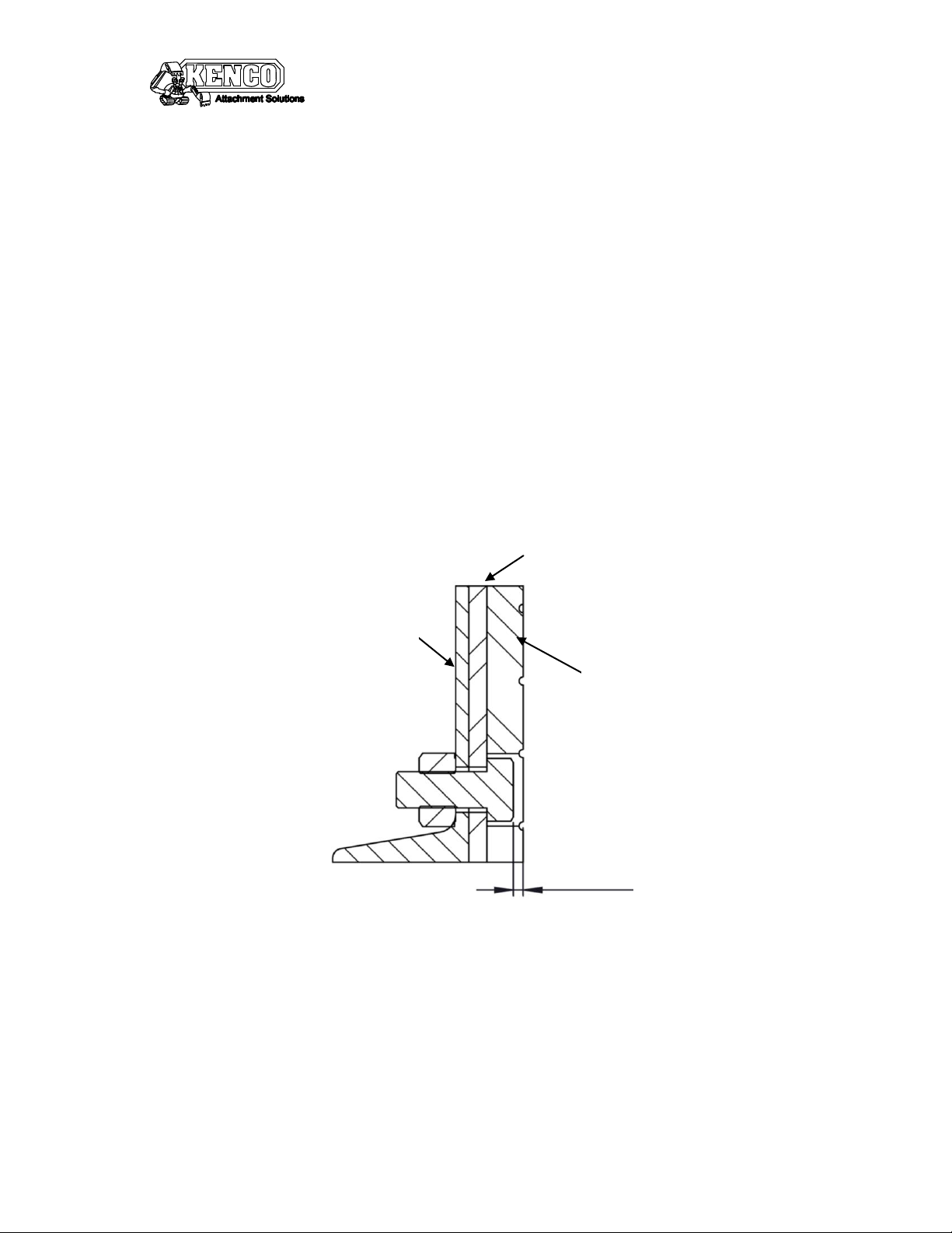
4. Pads –Replace if:
a. For units utilizing urethane gripping pads, if surface of any given mounting
bolt is not at least 3/32” below the surface of the pad,.
b. Any de-lamination of the pad from the backing plate.
c. Any scarring, chunking, or missing pad material constituting a total
combined loss of surface area greater than 3 sq. in. per pad.
d. Any single scar, chunk, or missing pad face that is greater than 1 sq. in per
pad.
Este manual sirve para los siguientes modelos
1
Tabla de contenidos
Otros manuales de Herramientas eléctricas de Kenco


