Keiser M3 Manual de usuario

USER MANUAL
USER MANUAL
UNPACKING THE BIKE
Carefully remove the bike from the cardboard box. Lay out all the components and check to assure
all parts are present and undamaged. If parts are missing or damaged contact your local dealer,
distributor or Keiser Corporation Service Department. After unpacking and verifying parts, you are
ready to start your assembly. You need an area that is free of dirt, dust or other foreign material that
could impair the assembly of your bike.
BEFORE ASSEMBLING
Always follow the steps in this manual as you assemble your bike. Do not skip, substitute or modify
any steps or procedures of this assembly, as doing so could result in personal injury and will void your
warranty. We have put a number of precautions in this manual.
NOTE: Informs you about things we recommend you do or are aware of, before
performing the assembly. These notes are placed in the manual to aid you during a
certain procedure or to make you aware of any general mandatory actions or information.
WARNING: This symbol appearing throughout this manual means PAY ATTENTION! BE
ALERT! When you see this warning symbol, your safety is involved. It is being used to
call attention to POTENTIAL hazards that could result in personal injury or loss of life.
1
PRE-ASSEMBLY INSTRUCTIONS .....................................................
ASSEMBLY INSTRUCTIONS ..............................................................
M3 HANDLEBAR INSTALLATION ......................................................
M3+ HANDLEBAR INSTALLATION ..................................................
FLYWHEEL GUARD INSTALLATION ..................................................
CHECKING FOR PROPER OPERATION ............................................
SAFETY INFORMATION AND INSTRUCTIONS .................................
BIKE FITTING .....................................................................................
RESISTANCE/COMPUTER OVERVIEW .............................................
CALIBRATION INFORMATION ...........................................................
PREVENTITIVE MAINTENANCE CHART ...........................................
WARRANTY TERMS ...........................................................................
1
4
6
7
9
11
11
12
15
17
18
19
TABLE OF CONTENTS
Torque wrench (Minimum 45 Nm / 35 ft-lb) 16mm, or 5/8” crowfoot
4” extension 5mm Allen Wrench
15mm open-end wrench 6mm Allen Wrench
16mm, or 5/8” open-end wrench Paste or spray wax (used to clean after assembly)
#2 Phillips screwdriver Clean cloth
15mm crowfoot LPS #3 Heavy Duty Rust Inhibitor w/straw
2 - 10mm Wrenches
TOOLS YOU WILL NEED
NOTE: The substitution or modification of any part or component,
other than what is approved by Keiser, will void your warranty.

PARTS INVENTORY
A - M3 Handlebar Assembly (550815) I - 5 Socket Head Cap Screws M6x1 X 20 SS (9502)
B - Base Frame (550814) J - 2 Socket Head Cap Screws M8x1.25 X 12 SS (9513)
C - Bike Frame (550819/550820) K - Computer (models with computer only)
D - Flywheel (555003) L - Flywheel Guard
E - 2-Pedals / 1- Loctite 242 (540831) M - Flywheel Guard Clamp (555025)
F - Hubcap (555005) N - Hex Head Screw M6x1 X45 SS (9525)
G - 4 Acorn Nuts (555022) O - Hex Nut M6x1SS (9508)
H - 4 Washers (9384) P - Hub Cover Decals
B
C
E
F
G
H
J
I
A
K
Transport Wheels
L
N
P
O
M
2
NOTE: The M3+ Parts Inventory will not include item A - M3 Handlebar Assembly (550815).
It will include items A1-A5, and will require following the M3+ Handlebar Assembly procedure.
Item P - Hub Cover Decals, will be shipped with, and are to be installed on M3/M3+ sold
within the European Union only.
M3+ HANDLEBAR
PARTS INVENTORY
A1 - M3+ Handlebar Assembly (550835)
A2 - Sweat Guard Cover (555080)
A3 - Bottom Slide (555026)
A4 - Handlebar Spacer (555031)
A5 - L-Handle Assembly (550828)
A1
A3
A2
A5
A4

1 - Saddle 8 - Resistance Shifter
2 - Forward/Backward Seat Adjusment Handle 9 - Multi-Placement Handlebars
3 - Up/Down Seat Adjustment 10 - Sweat Guard
4 - Belt Cover 11 - Water Bottle Holder
5 - Base Frame 12 - Shimano™ Combo Pedals
6 - Multi-Function Computer System 13 - Transport Wheels
7 - Up/Down Handlebar Adjustment T-Handle 14 - Flywheel
1 - Fore/Aft Adjustable Handlebars
2 - Fore/Aft Adjustment L-Handle
Total Bike Weight: M3 - 85 lbs (38.6 kg) / M3+ - 91 lbs (41.27kg)
M3 Footprint: Length 49 in (1245 mm) x Width 25.75 in (654 mm)
M3+ Footprint: Length 49.5” to 58.5” (1 257 mm to 1 485 mm)
x Width 25.75 in (654 mm)
12
10
9
6
8
7
2
3
13
5
1
11
14
4
1
2
M3+ INDOOR CYCLE
M3/M3+ INDOOR CYCLE
3

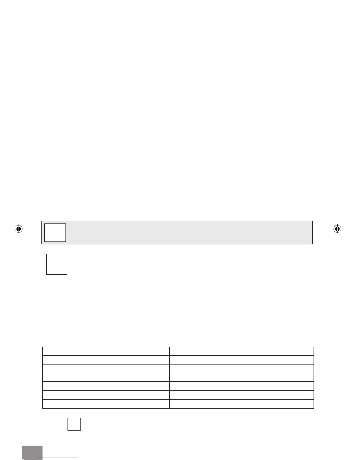
ASSEMBLING BIKE TO BASE FRAME
Step 1: Carefully lower the bike onto the base frame over the base screws, with the front
of the bike facing the transport wheels on the Base Frame. (Fig. 1)
Step 2: Insert one washer on each of the four base frame studs. (Fig. 1)
Step 3: Install the acorn nuts on the studs and hand tighten. Torque the acorn nuts with a
16mm or 5/8” crowfoot and torque wrench to 45 Nm (35 ft-lbs) using a 16mm,
or 5/8 inch open-end wrench to hold in position. (Fig. 2)
BIKE ASSEMBLY
4
3
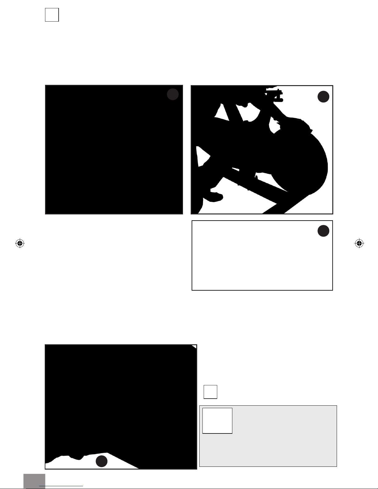
ASSEMBLING FLYWHEEL, HUB, AND HUB CAP
Step 1: Before starting the assembly of the ywheel, hub, and hub cap, make sure that
the shifter lever is in the downward position. (Fig. 3)
NOTE: Not following this step may scratch the ywheel.
Step 2: Remove the plastic wrapping from around the axle, hub, and hub cap. Remove
the hub cap. Obtain the 5 socket head cap screws (M6x1 X 20 SS) and 5mm Allen
wrench. (Fig. 4) Remove the ywheel from its foam envelope.
1 2
4
Step 1: Unwrap the pedal set and Loctite 242,
obtain the Torque wrench, 15mm crowfoot, 4”
extension, and 15mm open-end wrench.
NOTE: Use the foam envelope to handle the ywheel during assembly.
Step 3: Carefully slide the ywheel between the two magnets (Fig 4. & Fig. 5) and onto the
hub at the same time. Make sure that the ywheel is ush against the hub and align the
screw holes.
Step 4: Holding the ywheel in position with one hand, install the hubcap and align the
screw holes. Install the socket head cap screws (M6x1 X 20 SS). Using the 5mm Allen
wrench, tighten the screws in a star pattern until snug (as shown in Fig. 6).
Step 5: After 5 hub screws have been
installed, apply 5 clear decals to each side of
the hub cover as shown (Fig. 6a).
56
WARNING!
Failing to install the pedals with Loctite 242,
or crossing the threads will damage them,
and could result in serious injury to the user.
7
NOTE: Left pedal is LH threads
and right pedal is RH threads.
Step 2: With a clean cloth, wipe the
threaded area of the pedals. Apply
Loctite 242 to the pedal threads. Install
the pedals into the crank arms, use the
15mm open-end wrench to tighten.
Finish with the torque wrench, 15mm
crowfoot, and 4” extension. Torque
pedals to 45 Nm (35 ft-lbs) (Fig. 7).
ASSEMBLING PEDAL TO CRANK ARM
6a
5

8
9
Computer mounting screw
MOUNTING M3 HANDLEBAR ASSEMBLY
FOR M3+ HANDLEBAR ASSEMBLY, PROCEED TO PG. 7
NOTE: If installing computer please do so before mounting the handlebars.
10
Step 1: Obtain the handlebar assembly,
6mm Allen wrench, and the socket head
cap screws (M8x1.25 X 12 SS). Observe the
location of the two mounting anges on
the handlebar post. Place the handlebar
assembly on the post mounts, aligning the
mounting holes. (Fig. 10).
11 Step 2: Tilt the handlebar assembly slightly
to place the socket head cap screws
(M8x1.25 X 12 SS) into the mounting
holes (Fig. 11). Once each screw has been
started, place the palm of one hand on
the center of the handlebar pressing rmly
and evenly onto the handlebar post. With
the other hand tighten each screw with the
Allen wrench until the head of each screw
just makes contact with each hole. Now
tighten each screw evenly.
MOUNTING COMPUTER (MODELS WITH COMPUTER)
Step 1: Obtain the #2 Phillips screwdriver and remove the computer mounting screw
from the handlebar tube.
Step 2: Coil the computer cable into the computer mount cavity (Fig. 8).
Step 3: Slide the computer up into the two locking ears. Insert and secure the screw you
removed in Step 1 using the #2 Phillips screwdriver (Fig. 9).
6

MOUNTING M3+ HANDLEBAR ASSEMBLY
5 6
3 4
Step 1: Remove screws from both sides of the Sweat Guard.
Step 2: Slide on the Guard Cover and snap it over and align with the mounting holes of
the Sweat Guard.
Step 3: Replace both screws, but do not over tighten.
Step 4: Remove the four (6mm allen) screws four screws from the Handlebar Tube,
located below the computer mount.
Step 3: Using a 6mm Allen wrench, and the four screws, assemble the Bottom Slide to
the Handlebar Tube. Tighten rmly, making sure there is no gap between the Slide and the
Handlebar Tube (Fig. 6).
1 2
7

Step 7: Balance the Adjustable Handlebars on the Bottom Slide.
Step 8: Locate the L-Handle Assembly, you will need to disassemble it in the following
step.
Step 9: Using a 5mm Allen wench remove the Screw and Washer, releasing the Handle Stud.
Step 10: Clean Screw thread with alcohol, then apply Loctite 242 to leading edge of
screw thread for handle bar adjust screw.
Step 11: Assemble Handle Stud and the Handlebar Spacer.
Step 11: Use assembled Handle Stud and Handlebar Spacer to mount the Adjustable
Handlebars to the Bottom Slide.
1211
7 8
8
9Handle Stud
Spacer
10

FLYWHEEL GUARD INSTALLATION
Step 1: Make sure to have all parts and tools present prior to assembly.
Step 2: Assemble the brackets (B) to the tube (C) With the bolt and nut (A) nger tight.
PARTS INVENTORY
A) Bolt and Nut B) Brackets C) Tube
A
B
C
1 2
Step 3: (Next Page) Make sure the ywheel is centered in the middle of the 2x4 tube of the
base frame. Remove the two (6mm allen) screws and washers from the base frame. These
screws will be used to mount the ywheel guard in step 6.
Step 13: Hand Tighten the assembly.
Step 14: Fit the L-Handle to the Handle Stud. Position the L-Handle making sure that it is
pointing to the front of the M3+. Install the Screw and Washer. Make sure it is snug.
1413
15
9
Step 14: Loosen the L-Handle counter-clock wise. Slide the Handlebars back and forth,
making sure they can move freely and be locked into all positions on the Bottom Slide.
Otros manuales para M3
4
Este manual sirve para los siguientes modelos
1
Tabla de contenidos
Otros manuales de Bicicleta estática de Keiser

Keiser
Keiser M3i lite Manual de usuario

Keiser
Keiser M SERIES Instrucciones de instalación y funcionamiento

Keiser
Keiser REAR WHEEL DRIVE BIKE Manual de usuario

Keiser
Keiser m3 TBT Manual de usuario

Keiser
Keiser M3 Manual de usuario

Keiser
Keiser M3i lite Manual de usuario

Keiser
Keiser M SERIES Instrucciones de instalación y funcionamiento

Keiser
Keiser M3 Manual de usuario

Keiser
Keiser M3 Guía de solución de problemas

Keiser
Keiser M3X Manual de usuario


 Manual de usuario")


