KCI RADF13 Manual de usuario

Ver 1.2
USER'S MANUAL
RADS11 / RADF13
RADIO REMOTE CONTROL SYSTEMS
0341
RADS11 and RADF13 Users Manual ver1.2.doc
KCI Hoists Corp. reserves the right to modify this information without prior notification.
Page 1 of 20

I N D E X
Pg.
CONFORMITY DECLARATION.................................................................................... 3
1 DESCRIPTION .......................................................................................................... 4
2 SAFETY PRECAUTIONS......................................................................................... 5
2.1 What you must do .............................................................................................. 5
2.2 What you must not do........................................................................................ 5
3 INSTALLATION ....................................................................................................... 6
3.1 The BC60K battery charger............................................................................... 6
3.2 Receiver ............................................................................................................. 7
3.3 Starting-up ....................................................................................................... 11
3.4 Spurious Disturbance....................................................................................... 13
4 USE........................................................................................................................... 14
5 HOW TO ACCESS TO THE HOIST CONDITION MONITORING UNIT IN
RADF13 SYSTEM. SERVICE MODE. ..................................................................15
5.1 General Description of Service Mode .............................................................15
5.2 Entering the Service mode............................................................................... 15
5.3 Keys for moving within the Menus. ................................................................ 16
5.4 Switching from Tared Load to Actual Load.................................................... 16
5.5 Resetting the Tared Load................................................................................. 16
5.6 Exiting Service mode....................................................................................... 17
5.7 Messages originated in the receiver................................................................. 17
6 MAINTENANCE ..................................................................................................... 18
6.1 Precautions....................................................................................................... 18
6.2 Preventive maintenance ................................................................................... 18
6.3 Locating Break-downs..................................................................................... 19
7 Drilling pattern sheet. ............................................................................................... 20
INDEX OF FIGURES
Figure 1 Battery charger BC60K ................................................................................6
Figure 2 Receiver Box dimensions ............................................................................. 7
Figure 3 Receiver to Power Electric Circuit connection............................................. 8
Figure 4 Connection diagram for RADS11................................................................. 9
Figure 5 Connection diagram for RADF13............................................................... 10
Figure 6 RADS11 and RADF13 transmitters ........................................................... 12
Figure 7 Entering the Service mode.......................................................................... 15
Figure 8 LCD Display in Service Mode.................................................................... 16
Figure 9 Pushbutton as a Key board for Hoist Condition Monitoring Unit.............. 16
Figure 10 LCD representing Tared Load .................................................................... 16
RADS11 and RADF13 Users Manual ver1.2.doc
KCI Hoists Corp. reserves the right to modify this information without prior notification.
Page 2 of 20

CONFORMITY DECLARATION
KCI Hoists corp.
Ruununmyllyntie 13
FIN-13210 Hämeenlinna. Finland
NIF A-20-036.018
Phone: +358 (0)20 427 11
FAX: +358 (0)20 427 3399
And in its name,
Mr. Ari Kiviniitty, Managing Director,
declares, conscious of complete responsibility, that the product
Remote Control KCI Hoists Corp.
RADS11 / RADF13
Composed by the transmitters
RAD-TS or RAD-TF
plus receivers
RAD-RS or RAD-RF,
is in conformity with the following standards
ETSI EN 300220:2000, ETS EN301489-3:2000
EN 55022:1994,
EN 61000-4-2:1995, EN 61000-4-3:1996, EN 61000-4-4:1995
EN 61000-4-5: 1995, EN 61000-4-6:1996, EN 61000-4-11:1994,
EN 61000-3-2:1995,
EN 50178:1998
EN 60204-32:1998, EN 60529:1991
PrEN 13557:1999, PrEN 12077-1:1996
and therefore with all essential requirements and provisions of the
Directive 1999/5/EC of the European
Parliament and of the Council of March 9, 1999
on Radio and Telecommunications Terminal Equipment
and with
the requirements of the 93/44/EEC Machinery Directive.
Hämeenlinna, 21st of Jun 2002
Signed: Ari Kiviniitty
Managing Director
RADS11 and RADF13 Users Manual ver1.2.doc
KCI Hoists Corp. reserves the right to modify this information without prior notification.
Page 3 of 20

1 DESCRIPTION
The RADS11 and RADF13 push-button transmitter type, radio remote control systems,
are designed for the remote control of hoists and cranes, and are particularly suitable for
applications when the operator needs to be able to choose the best location from which
to carry out an operation.
The system consists of a transmitter for selecting commands and a receiver that is
connected to the electrical system of the machine to be operated. The system also comes
with a battery charger and two rechargeable batteries.
The main specifications for RADS11 / RADF13 systems are:
RADS11 / RADF13 Systems In EU countries In North America
Frequency band 869.7 to 870MHz 902 to 928MHz
Baud rate 7200 bps
Channel separation 12.5 KHz 25 KHz
Channel Occupation 7.2 KHz
Modulation FM (GMSK)
Response Time 100 ms
Temperature range -20ºC to +65ºC -4F to 150F
The RAD-TS and RAD-TF transmitters
Transmission power <5 mW
Protection IP65 NEMA 4
The RAD-RS and RAD-RF receivers
Power supply 48 Vac, 115 Vac, 230Vac ± 10%, 50/60 Hz
Consumption 30 W
Relays 230 Vac/8 A
Protection IP55 NEMA 12
Communication CL20mA (RAD-RF only)
Protection against electric shock Class II according EN50178 (1997)
The BC60K battery charger
Power supply (± 10%) 230 Vac 50/60Hz 115Vac, 50/60 Hz
The BT06K batteries
Voltage 4.8 V
Capacity 700 mAh, NiMH
Charging temperature 5ºC to 35ºC 41F to 95F
Operating Time 12h at 50% RAD-TS model.
8h at 50% RAD-TF model.
RADS11 and RADF13 Users Manual ver1.2.doc
KCI Hoists Corp. reserves the right to modify this information without prior notification.
Page 4 of 20

SAFETY PRECAUTIONS
These instructions must be read carefully in order to install and use the radio
control system properly and to keep it in perfect working condition and to reduce
the risks of misuse.
Do not use this system on machines for the lifting of persons or in potentially
explosive atmospheres.
Any use other than that specified in this manual is dangerous. The following
instructions must be strictly adhered to.
Important note: To comply with FCC RF exposure compliance requirements, this
device and its antenna must not be operating in conjunction with any other
antenna or transmitter.
WARNING:
Modifications to this equipment are expressly forbidden by the FCC Rules.
Changes or modifications not expressly approved by the party responsible for
compliance may void the user's authority to operate this equipment.
1.1 What you must do
Strictly adhere to the instructions for installation contained in this manual.
Make sure that professional and competent personnel carry out the installation.
Ensure that all site and prevailing safety regulations are followed.
Make sure that this manual is permanently available to the operator and maintenance
personnel.
Keep the transmitter out of reach of unauthorised personnel.
Remove the transmission key when the system is not in use.
At the beginning of each work shift, check to make sure that the STOP button and
other safety measures are working.
When in doubt, press the STOP button.
Whenever several systems have been installed, make sure the transmitter you are going
to use is the correct one. Identify the machine controlled on the label for this purpose
on the transmitter.
Service the equipment periodically.
When carrying out repairs, only use spare parts supplied by the manufacturer dealers.
Use only battery pack BT06K 4.8V 700mAh.
1.2 What you must not do
Never make any changes to the radio control system, which have not been engineered
and approved by the manufacturer.
Never power the equipment other than with the specified power supply.
Never allow unqualified personnel to operate the equipment.
RADS11 and RADF13 Users Manual ver1.2.doc
KCI Hoists Corp. reserves the right to modify this information without prior notification.
Page 5 of 20

After use, never leave the equipment ON-state. Always use the transmission key or the
STOP button to avoid accidentally activating functions.
Do not use the radio control system when visibility is limited.
Avoid knocking, bumping or dropping the transmitter.
Do not use the equipment if failure is detected.
2 INSTALLATION
2.1 The BC60K battery charger
Connect the charger to the power source using the power source and the cable supplied.
The red LED, in the middle, should light up indicating power ON.
When installing the battery charger, bear in mind that the batteries must be charged at
temperatures over 5ºC (41F) and that the power supply must be left on all night. Also
remember that the charger must not be left in direct sunlight, as the batteries may not
become fully charged at temperatures exceeding 35ºC (95F).
Place the batteries in the charger.
There is green LED on top of each
battery. Each LED should light up,
indicating that recharging is in
process. Complete recharging takes
approximately 12 hours. After
charging process is finished, the
green LED is turned OFF. The
batteries may remain in the charger
for an unlimited period of time.
Figure 1 Battery charger BC60K
The capacity of the batteries decreases with use. Their life span is estimated to be 500
recharging cycles, but this depends largely on the conditions of use, for which the
following is recommended:
Do not recharge the battery until it is completely empty. The transmitter will indicate
this when to recharge the batteries.
Always charge the batteries at temperatures between 5º(41F) and 35ºC (95F).
Avoid short-circuits between the battery contacts. Do not carry charged batteries in
toolboxes or next to other metal objects (keys, coins, etc.).
Always keep contacts clean.
Never leave batteries in direct sunlight.
RADS11 and RADF13 Users Manual ver1.2.doc
KCI Hoists Corp. reserves the right to modify this information without prior notification.
Page 6 of 20

2.2 Receiver
Make sure that the crane is stopped for the entire duration of the installation
process, keep the work area free and wear protective clothing.
Park the crane and position at end stop, (if these are not available use appropriate
signs), at a suitable distance so that other cranes do not hit it on the same runway.
Check the power-supply voltage and turn off the main switch.
Find a suitable location for the receiver, away from any intense radioelectric disturbance
sources and install the receiver using the 4 elastic rubber absorbers, (M8) supplied with
the set.
6,7’’(inch)
10’’ (inch)
Figure 2 Receiver Box dimensions
The receiver must be placed free of shielding. Metal parts that could obstruct reception
of the radio signal must be avoided.
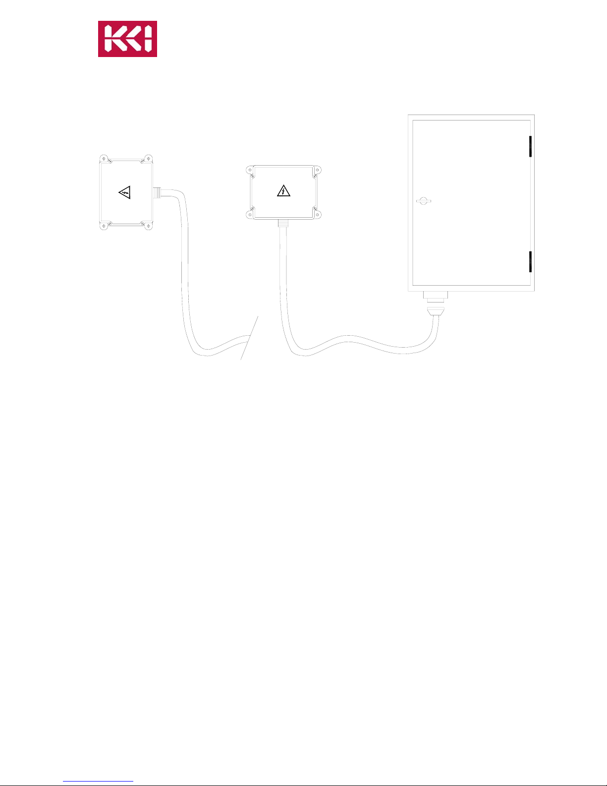
The way to connect the receiver box to the crane's electrical installations is using a cable
with a terminal multiple-pole connector:
Note: See attached drilling pattern sheet.
RADS11 and RADF13 Users Manual ver1.2.doc
KCI Hoists Corp. reserves the right to modify this information without prior notification.
Page 7 of 20

Figure 3 Receiver to Power Electric Circuit connection
The contacts of KSTOP1 and KSTOP2 (KSTOP1+KSTOP2=STOP) relays are in series
and must be connected to the main contactor coil circuit.
The K2/START is activated once the start-up command is held down.
The K1/SAFETY relay is a security relay which is activated when any of the other
function control relay are activated.
The receiver is a class II device, according EN50178, containing a functional earth
connection. A (in Europe green-yellow) ground cable is not recommended for this earth
connection.
The power supply and relays must be protected against current overload with convenient
electric devices, limiting the maximum input/ output current to their limits: 1A fuse is
provided in the receiver circuit board for power supply. 8A fuse(s) has to be provided in
the crane control panel for the for the output relays.
RADS11 and RADF13 Users Manual ver1.2.doc
KCI Hoists Corp. reserves the right to modify this information without prior notification.
Page 8 of 20

Figure 4 Connection diagram for RADS11
Remember to connect the ground cable.
Use only the approved cables.
Select the appropriate voltage on the receiver, (230, 115 or 48 Vac).
RADS11 and RADF13 Users Manual ver1.2.doc
KCI Hoists Corp. reserves the right to modify this information without prior notification.
Page 9 of 20

Figure 5 Connection diagram for RADF13
Remember to connect the ground cable.
Use only the approved cables.
Select the appropriate voltage on the receiver, (230, 115 or 48 Vac).
RADS11 and RADF13 Users Manual ver1.2.doc
KCI Hoists Corp. reserves the right to modify this information without prior notification.
Page 10 of 20
Este manual sirve para los siguientes modelos
6
Tabla de contenidos