JVC UX-T770R Manual de usuario

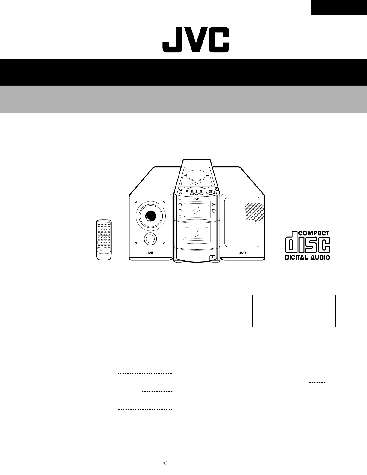
SERVICE MANUAL
MICRO COMPONENT SYSTEM
No.20993
Jun. 2001
COPYRIGHT 2001 VICTOR COMPANY OF JAPAN, LTD.
UX-T770R
UX-T770R
Contents
Safety Precautions
Important for laser products
Preventing static electricity
Disassembly method
Adjustment method
Flow of functional operation
TOC read
Maintenance of laser pickup
Replacement of laser pickup
Description of major ICs
1-2
1-3
1-4
1-5
1-16
1-20
1-21
1-21
1-22
Area Suffix
E ------ Continental Europe
EN ------- Northern Europe

UX-T770R
1-2
1. This design of this product contains special hardware and many circuits and components specially for safety
purposes. For continued protection, no changes should be made to the original design unless authorized in
writing by the manufacturer. Replacement parts must be identical to those used in the original circuits. Services
should be performed by qualified personnel only.
2. Alterations of the design or circuitry of the product should not be made. Any design alterations of the product
should not be made. Any design alterations or additions will void the manufacturer`s warranty and will further
relieve the manufacture of responsibility for personal injury or property damage resulting therefrom.
3. Many electrical and mechanical parts in the products have special safety-related characteristics. These
characteristics are often not evident from visual inspection nor can the protection afforded by them necessarily
be obtained by using replacement components rated for higher voltage, wattage, etc.Replacement parts which
have these special safety characteristics are identified in the Parts List of Service Manual. Electrical
components having such features are identified by shading on the schematics and by ( ) on the Parts List in
the Service Manual. The use of a substitute replacement which does not have the same safety characteristics
as the recommended replacement parts shown in the Parts List of Service Manual may create shock, fire, or
other hazards.
4. The leads in the products are routed and dressed with ties, clamps, tubings, barriers and the like to be
separated from live parts, high temperature parts, moving parts and/or sharp edges for the prevention of
electric shock and fire hazard. When service is required, the original lead routing and dress should be
observed, and it should be confirmed that they have been returned to normal, after re-assembling.
5. Leakage currnet check (Electrical shock hazard testing)
After re-assembling the product, always perform an isolation check on the exposed metal parts of the product
(antenna terminals, knobs, metal cabinet, screw heads, headphone jack, control shafts, etc.) to be sure the
product is safe to operate without danger of electrical shock.
Do not use a line isolation transformer during this check.
Plug the AC line cord directly into the AC outlet. Using a "Leakage Current Tester", measure the leakage
current from each exposed metal parts of the cabinet, particularly any exposed metal part having a return
path to the chassis, to a known good earth ground.Any leakage current must not exceed 0.5mA AC (r.m.s.).
Alternate check method
Plug the AC line cord directly into the AC outlet. Use an AC voltmeter having, 1,000 ohms per volt or more
sensitivity in the following manner. Connect a 1,500 10W resistor paralleled by a 0.15 F AC-type capacitor
between an exposed metal part and a known good earth ground.
Measure the AC voltage across the resistor with the AC
voltmeter.
Move the resistor connection to each exposed metal part,
particularly any exposed metal part having a return path to
the chassis, and meausre the AC voltage across the resistor.
Now, reverse the plug in the AC outlet and repeat each
measurement.Voltage measured any must not exceed 0.75 V
AC (r.m.s.).This corresponds to 0.5 mA AC (r.m.s.).
1.This equipment has been designed and manufactured to meet international safety standards.
2. It is the legal responsibility of the repairer to ensure that these safety standards are maintained.
3. Repairs must be made in accordance with the relevant safety standards.
4. It is essential that safety critical components are replaced by approved parts.
5. If mains voltage selector is provided, check setting for local voltage.
Good earth ground
Place this
probe on
each exposed
metal part.
AC VOLTMETER
(Having 1000
ohms/volts,
or more sensitivity)
1500 10W
0.15 F AC TYPE
!
Burrs formed during molding may
be left over on some parts of the
chassis. Therefore, pay attention to
such burrs in the case of
preforming repair of this system.
In regard with component parts appearing on the silk-screen printed side (parts side) of the PWB diagrams, the
parts that are printed over with black such as the resistor ( ), diode ( ) and ICP ( ) or identified by the " "
mark nearby are critical for safety.
When replacing them, be sure to use the parts of the same type and rating as specified by the manufacturer.
(Except the J and C version)

UX-T770R
1-3
Important for laser products
1.CLASS 1 LASER PRODUCT
2.DANGER : Invisible laser radiation when open and inter
lock failed or defeated. Avoid direct exposure to beam.
3.CAUTION : There are no serviceable parts inside the
Laser Unit. Do not disassemble the Laser Unit. Replace
the complete Laser Unit if it malfunctions.
4.CAUTION : The compact disc player uses invisible laser
radiation and is equipped with safety switches which
prevent emission of radiation when the drawer is open and
the safety interlocks have failed or are de
feated. It is dangerous to defeat the safety switches.
5.CAUTION : If safety switches malfunction, the laser is able
to function.
6.CAUTION : Use of controls, adjustments or performance of
procedures other than those specified herein may result in
hazardous radiation exposure.
VARNING : Osynlig laserstrålning är denna del är öppnad
och spårren är urkopplad. Betrakta ej strålen.
VARO : Avattaessa ja suojalukitus ohitettaessa olet
alttiina näkymättömälle lasersäteilylle.Älä katso
säteeseen.
ADVARSEL : Usynlig laserstråling ved åbning , når
sikkerhedsafbrydere er ude af funktion. Undgå
udsættelse for stråling.
ADVARSEL : Usynlig laserstråling ved åpning,når
sikkerhetsbryteren er avslott. unngå utsettelse
for stråling.
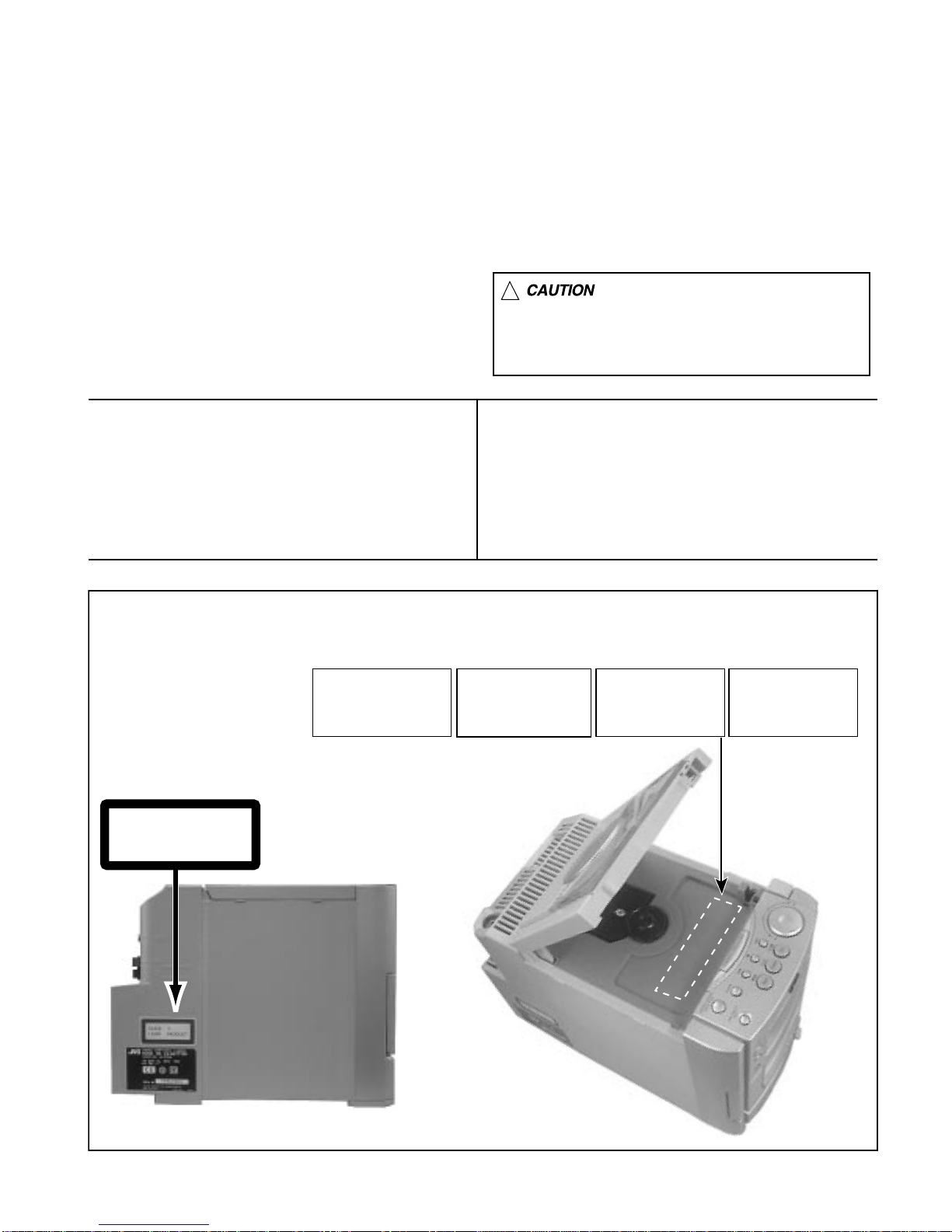
REPRODUCTION AND POSITION OF LABELS
WARNING LABEL
DANGER : Invisibie laser radiation
when open and interlock or
defeated.
AVOID DIRECT EXPOSURE TO
BEAM (e)
VARNING : Osynlig laserstrålning är
denna del är öppnad och spårren är
urkopplad. Betrakta ej strålen. (s)
VARO : Avattaessa ja suojalukitus
ohitettaessa olet alttiina
näkymättömälle lasersäteilylle.Älä
katso säteeseen. (d)
ADVARSEL :Usynlig laserstråling
ved åbning , når
sikkerhedsafbrydere er ude af
funktion. Undgå udsættelse for
stråling. (f)
CLASS 1
LASER PRODUCT
!Please use enough caution not to
see the beam directly or touch it
in case of an adjustment or operation
check.

UX-T770R
1-4
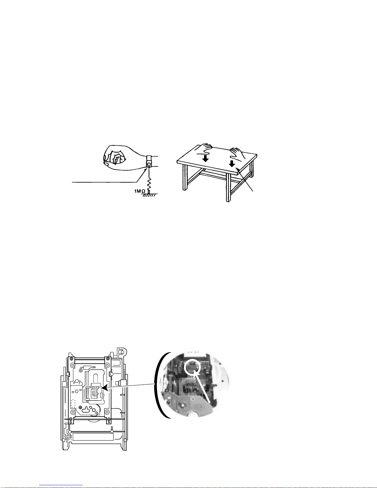
Conductive material
(conductive sheet) or iron plate
(caption)
Anti-static wrist strap
Preventing static electricity
Electrostatic discharge (ESD), which occurs when static electricity stored in the body, fabric, etc.is discharged,
can destroy the laser diode in the traverse unit (optical pickup). Take care to prevent this when performing repairs.
1.2. Handling the traverse unit (optical pickup)
1. Do not subject the traverse unit (optical pickup) to strong shocks, as it is a sensitive, complex unit.
2. Cut off the shorted part of the flexible cable using nippers, etc. after replacing the optical pickup. For specific
details, refer to the replacement procedure in the text.Remove the anti-static pin when replacing the traverse
unit.Be careful not to take too long a time when attaching it to the connector.
3. Handle the flexible cable carefully as it may break when subjected to strong force.
4. It is not possible to adjust the semi-fixed resistor that adjusts the laser power. Do not turn it
1.1.3. Handling the optical pickup
1. In order to maintain quality during transport and before installation, both sides of the laser diode on the
replacement optical pickup are shorted. After replacement, return the shorted parts to their original condition.
(Refer to the text.)
2. Do not use a tester to check the condition of the laser diode in the optical pickup.The tester's internal power
source can easily destroy the laser diode.
1.1.2. Ground yourself
1. Use an anti-static wrist strap to release any static electricity built up in your body.
1.1.1. Ground the workbench
1. Ground the workbench by laying conductive material (such as a conductive sheet) or an iron plate over
it before placing the traverse unit (optical pickup) on it.
1.1. Grounding to prevent damage by static electricity
Static electricity in the work area can destroy the optical pickup (laser diode) in devices such as DVD players.
Be careful to use proper grounding in the area where repairs are being performed.

UX-T770R
1-5
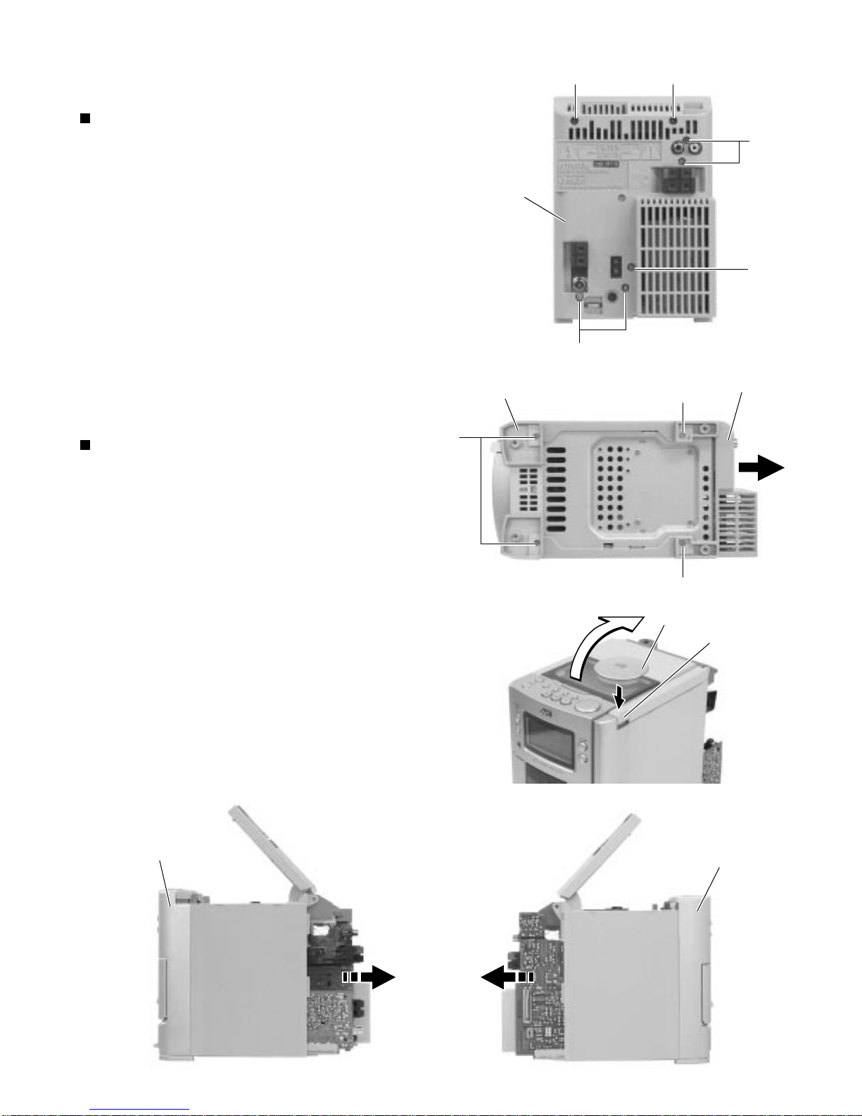
From behind the body, remove the seven screws A
retaining the rear panel.
After turning the body upside down, remove the two
screws Bretaining the rear panel.
Take out the rear panel from behind the body.
1.
2.
3.
Disassembly method
Removing the rear panel
(See Fig. 1 and 2)
After turning the body upside down, remove the two
screws Cretaining the front cabinet assembly.
After turning the body back to initial position, open
the CD door while pressing the upper OPEN button.
While moving the side panel (L) in the arrow
direction, remove the panel from the left side of the
body.
While moving the side panel (R) in the arrow
direction, remove the panel from the right side of the
body.
1.
2.
3.
4.
Removing the side panel (L) and (R)
(See Fig. 2 to 5)
AA
A
A
AFig. 1
Fig. 2
Fig. 3
Fig. 4Fig. 5
Rear panel
Front panel assembly
C
Side panel (L)
Side panel (R)
B
B
Rear panel
CD doorOPEN botton
Front panel assembly

UX-T770R
1-6
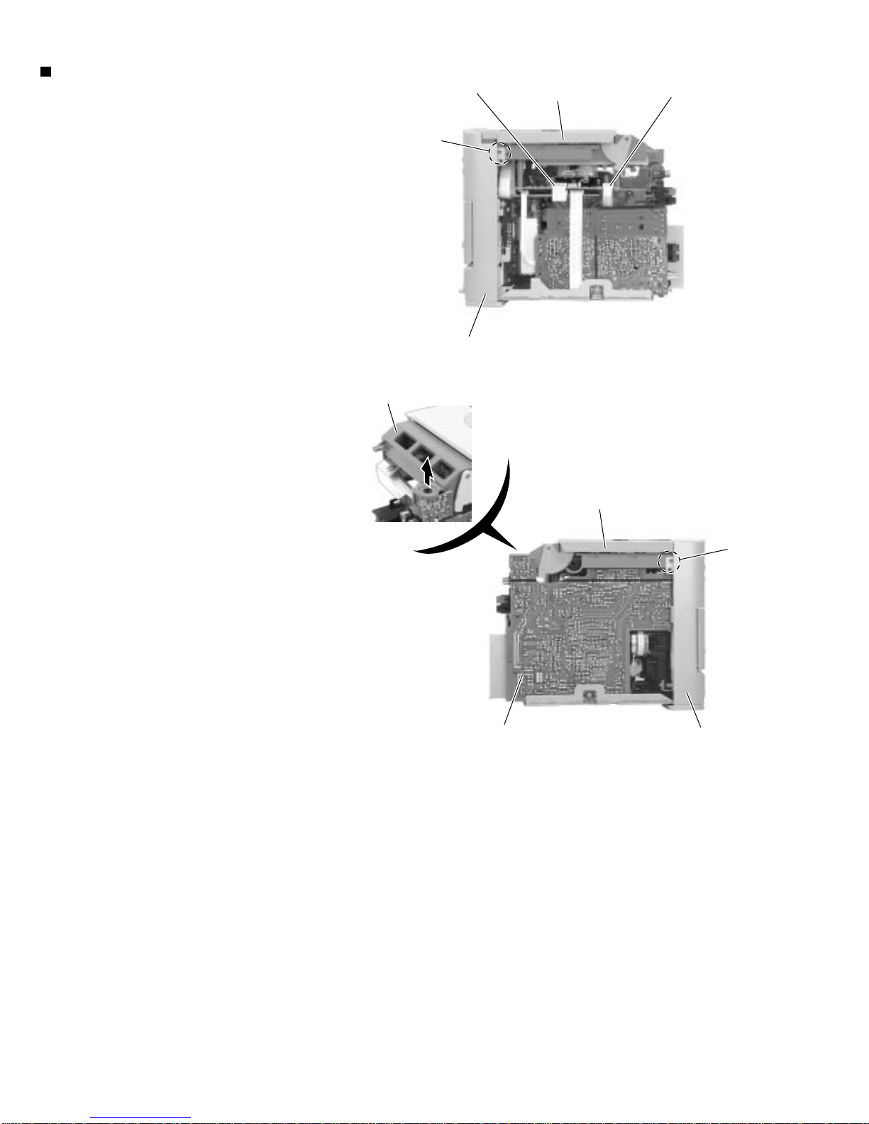
Remove the rear panel.
Remove the left and right side panels.
From the two connector CN603 and CN604 on the CD
servo control board, disconnect the card wires
outgoing from the connector CN304 on the power
amplifier board and the connector CN766 on the LCD
system CPU board.
Disengage the left and right engagements aand b
fixing the CD player unit by using a minus screw
driver, etc.
1.
2.
3.
4.
Removing the CD player unit
(See Fig. 6 to 8)
a
CD player unit CD servo control board
CN603
b
CD servo
control board
CN604
Fig. 6
Fig. 7
Front panel assembly
Fig. 8
CD player unit
Front panel assembly
Power amplifier board
CD player unit

UX-T770R
1-7
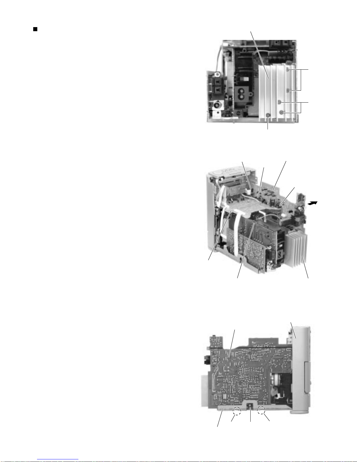
Remove the rear panel.
Remove the left and right side panels.
Remove the CD player unit.
Remove the five screws Dand Eretaining the heat
sink.
From the connector CN303 on the power amplifier
board, disconnect the card wire outgoing from the
connector CN34 on the head amplifier and
mechanism control board.
From the connector CN901 on the power supply
board, disconnect the connector wire outgoing from
the connector W306 on the power amplifier board.
Remove the one screw Fretaining the power
amplifier board.
Remove the power amplifier board from the two
connectors CN711 and CN712 on the LCD system
CPU board.
After removing the power amplifier board from the
key way c on the bottom chassis, take this board out
while raising it in the arrow direction.
1.
2.
3.
4.
5.
6.
7.
8.
9.
Removing the power amplifier board and
heat sink (See Fig. 9 to 11)
Power supply board
CN901
CN303
CN712
CN711
Heat sink
LCD system CPU board
Fig. 9
Fig. 10
Fig. 11
Heat sink
D
D
E
Power amplifier board
Power amplifier board Front panel assembly
c
cF
Bttom chassis

UX-T770R
1-8
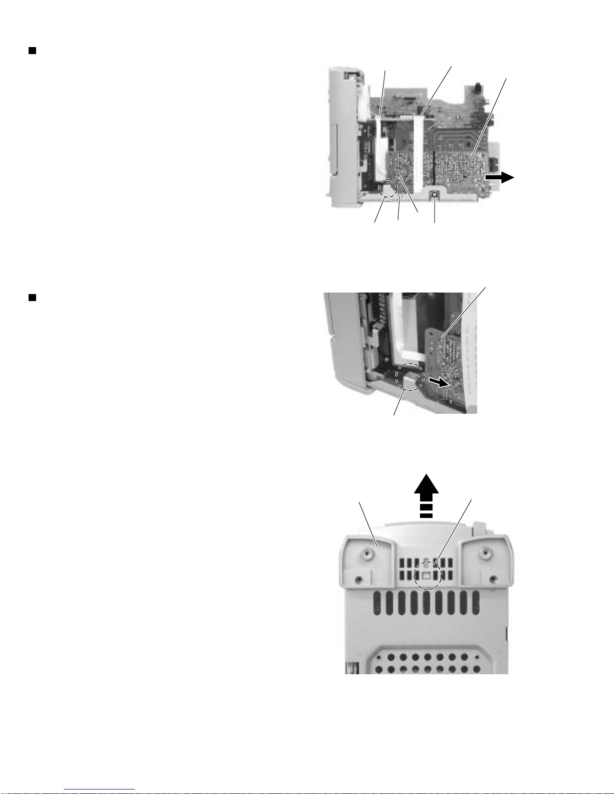
Remove the rear panel.
Remove the left and right side panels.
From the right side of the body, remove the one
screw Gretaining the tuner board.
From the connector CN1 and CN2 on the tuner
board, disconnect the card wire outgoing from the
connector CN701 and CN702 on the LCD system
CPU board.
Remove each tuner board backward while releasing
the joint d.
1.
2.
3.
4.
5.
Removing the tuner board
(See Fig. 12 and 13)
Remove the rear panel.
Remove the left and right side panels.
Remove the CD player unit.
Remove the power amplifier board and heat sink.
From the connector CN701 on the LCD system CPU
board, disconnect the card wire outgoing from the
connector CN1 on the tuner board.
From the bottom of the body, disengage the
engagement e fixing the front panel assembly in Fig.
14 while pressing in with a minus screw driver, eta.
1.
2.
3.
4.
5.
6.
Removing the front panel assembly
(See Fig. 12 and 14)
LCD system CPU board
CN701 Tuner board
G
Fig. 12
Fig. 13
Fig. 14
Joint d CN1
Joint d
Tuner board
e
Front panel assembly
CN702
CN2

UX-T770R
1-9
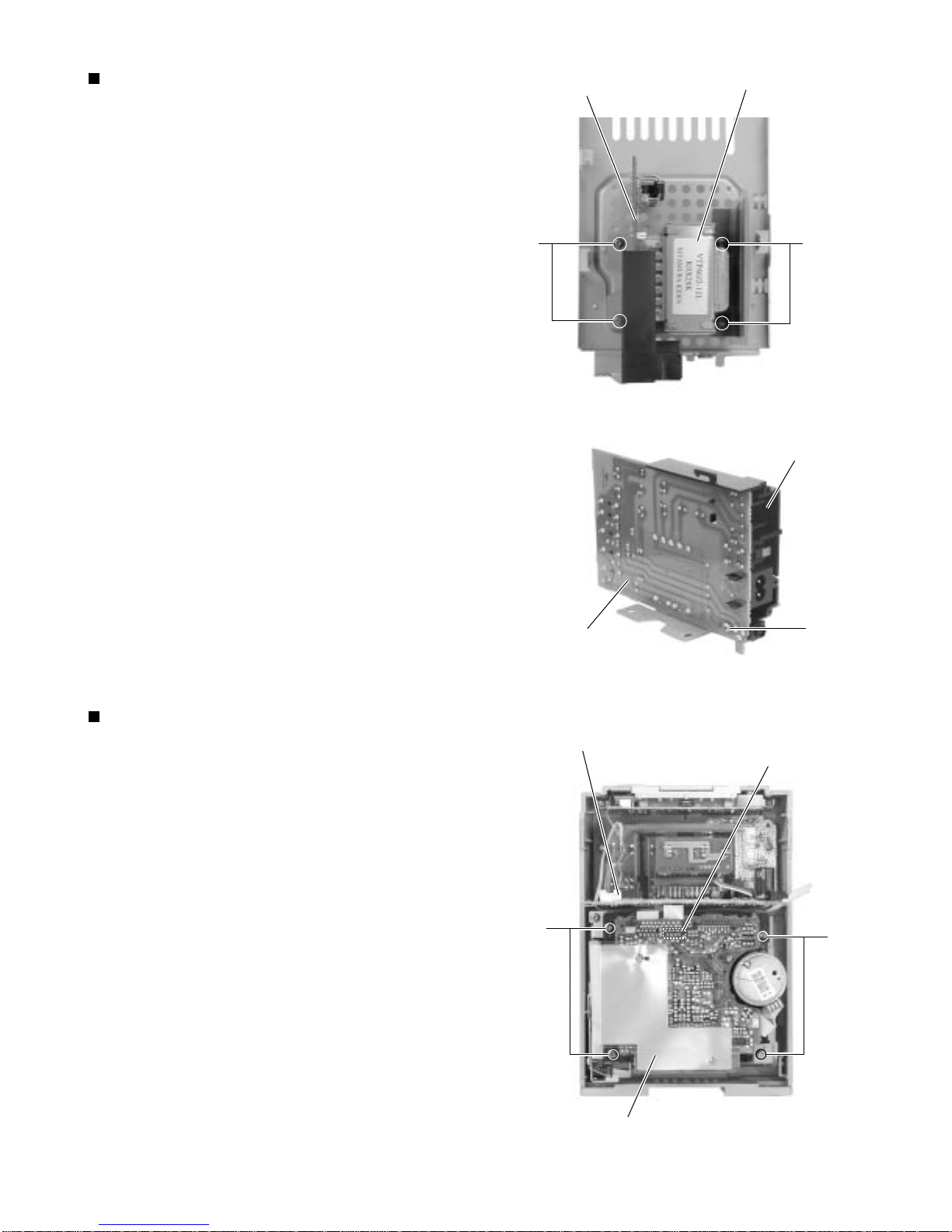
Remove the rear panel.
Remove the left and right side panels.
Remove the CD player unit.
Remove the power amplifier board and heat sink.
Remove the four screws Hretaining the power
transformer and power supply board and the one
screw Iretaining the jack holder.
1.
2.
3.
4.
5.
Removing the power transformer and
power supply board (See Fig. 15 and 16)
Remove the rear panel.
Remove the left and right side panels.
Remove the CD player unit.
Remove the power amplifier board.
Remove the front panel assembly.
From inside the front panel assembly, remove the
four screws Jand Kretaining the cassette
mechanism unit.
From the connector CN33 on the head amplifier and
mechanism control board, disconnect the card wire
outgoing from the connector CN731 on the LCD
system CPU board.
1.
2.
3.
4.
5.
6.
7.
Removing the cassette mechanism unit
(See Fig. 17)
LCD system CPU board
CN731
Cassette mechanism unit
Head amplifier & mechanism
control board
CN33
Fig. 15
Fig. 16
Fig. 17
HH
Power transformer
Power supply board
I
Jack holder
Power supply board
K
J

UX-T770R
1-10
Remove the rear panel.
Remove the left and right side panels.
Remove the CD player unit.
Remove the front panel assembly.
Remove the cassette mechanism unit.
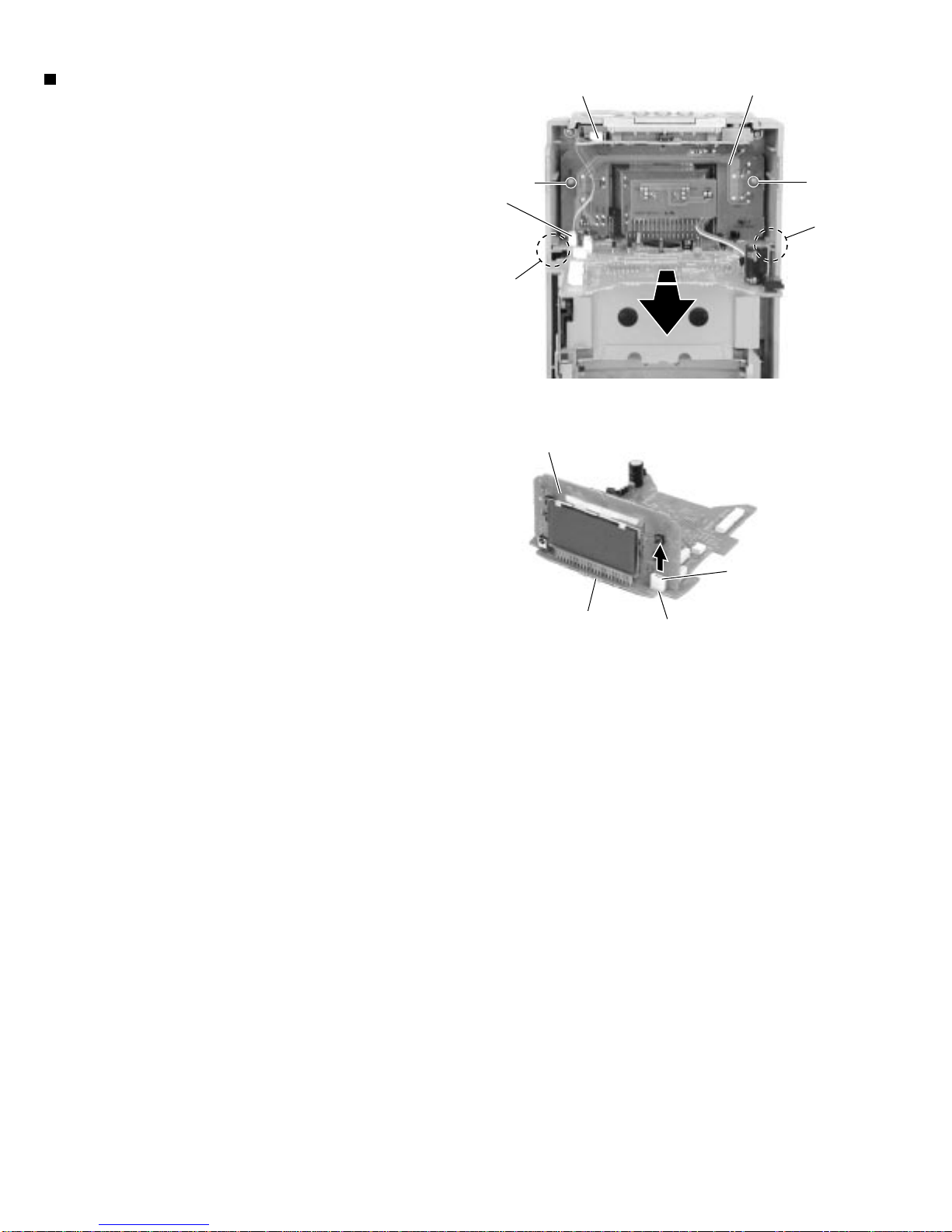
From inside the front panel assembly remove the two
screws Lretaining the function switch board.
From the connector CN782 on the LCD system CPU
board, disconnect the connector wire outgoing from
the connector CN802 on the operation switch board.
While sliding the two engagements ffixing the LCD
system CPU board, pull out this board.
After disconnect the connector CN801 on the
function switch board from the connector CN781 on
the LCD system CPU board, remove the respective
boards while pulling them upward.
1.
2.
3.
4.
5.
6.
7.
8.
9.
Removing the function switch board and
LCD system CPU board
(See Fig. 18 and 19)
LL
f
Operating switch board
CN802
LCD system
CPU board
CN782
Function switch board
LCD system CPU board CN781
CN801
Function switch board
Fig. 18
Fig. 19
f
Tabla de contenidos
Otros manuales de Sistema estéreo de JVC

JVC
JVC UX-F70MD Manual de usuario

JVC
JVC NX-D2 Manual de usuario

JVC
JVC RM-RXUV9RMD Manual de usuario

JVC
JVC UX-EP25 Manual de usuario

JVC
JVC UX-S59 Manual de usuario

JVC
JVC 0108NYMCREBET Manual de usuario

JVC
JVC MF-33L Manual de usuario

JVC
JVC UX-GP5 Manual de usuario

JVC
JVC UX-G30UW Manual de usuario

JVC
JVC LVT1364-002B Manual de usuario

JVC
JVC UX-H35 Manual de usuario

JVC
JVC PC-X250 Manual de usuario

JVC
JVC 0803AIMMDWJEM Manual de usuario

JVC
JVC UX-G355 Manual de usuario

JVC
JVC FS-GD7 Manual de usuario

JVC
JVC MX-GC5 Manual de usuario

JVC
JVC MX-JD8 Manual de usuario

JVC
JVC UX-J51 Manual de usuario

JVC
JVC CA-PCX290 Manual de usuario

JVC
JVC FS-G2 Guía del administrador