Jupitel G4000-2E2S Manual de usuario

Analogue Terminal Adaptor G4000-2E2S
USER’S
MANUAL

2
1. Product Introduction-----------------------------------------------------------3
1.1 Software------------------------------------------------------------------3
1.2 Protocol, Standard---------------------------------------------------------3
2. Electric Interface Operating Requirements---------------------------------4
2.1 Electric requirements----------------------------------------------------4
2.2 Interface requirements----------------------------------------------------4
2.3 Operating requirements---------------------------------------------------4
3. Structure Introduction-------------------------------------------------------- 5
3.1 ront Illustration---------------------------------------------------------5
3.2 Backside Illustration----------------------------------------------------5
4. Pac aging------------------------------------------------------------------------5
4.1 Size ----------------------------------------------------------------------5
4.2 Attachment-----------------------------------------------------------------5
5. Installation Guide---------------------------------------------------------------6
6. Settings--------------------------------------------------------------------------8
6.1 Home ---------------------------------------------------------------------8
6.2 WAN --------------------------------------------------------------------9
6.3 LAN---------------------------------------------------------------12
6.4 SIP---------------------------------------------------------------------15
6.5 CODECS----------------------------------------------------------------21
6.6 System----------------------------------------------------------------22
6.7 Download -----------------------------------------------------------26
6.8 Configuration ------------------------------------------------------27
6.9 Reset---------------------------------------------------------------28
7.0 Logout---------------------------------------------------------------29
7. Appendix. Dial Plans ---------------------------------------------------------30
7.1 Dial rules-------------------------------------------------------------31
7.2 What Ab out Ch a n g e M A C Add re ss- ----- -- - - ------- ---- -- -- --- --31
7.3 Wh at A bou t Re s et D ef a ul t - --- -- - -- --- --- - --- -- -- --- -- -- - --- --3 1
G4000-2E2S User’s Manual…………………..…………………………….

3
1.1 Software
Set phone by HTTP web browser
Upgrade by T TP HTTP
Support major G.726, G.7231, G.729, G.711U/A
Dynamic voice jitter buffer CNG (Comfort noise generation)
G.165 compliant 16ms echo cancellation
Tone generation and Local DTM re-generation according with ITU-T
E.164 dial plan and customized dial rules
SNMP V1/V2
1.2 Standard and Protocol
IEEE 802.3 /802.3 u 10 Base T / 100Base TX
Support Major codec G.726, G.7231, G.729, G.711U/A
SIP R C3261
TCP/IP: Internet transfer and control protocol
RTP: Real-time Transport Protocol
RTCP:Real-time Control Protocol
VAD/CNG save bandwidth
DHCP:Dynamic Host Configuration Protocol
PPPoE:PPP Protocol over Ethernet
DNS:Domain Name Server
T TP:ile Transfer protocol
HTTP:Hyper Text Transfer protocol
.
Product Introduction…………………………..…………………………….

4
2.1 Electric requirements:
Voltage:9V
Power adapter: output DC 9V/1000mA DC
Network interface:2X RJ-45 Ethernet Connectors
XS: 2 X RJ11 Analogue Terminals
2.2 Interface requirements:
Wan: 10M/100M
XS
Line eed Voltage :> =42V
Ring Voltage :> =45V.
Ring Current : >=30mA
2.3 Operating requirements:
Operation temperature: 0 to 50° C (32° to 122° )
Storage temperature: -30° to 65° C (-22° to 149° )
Humidity: 10 to 90% no dew
Electric Inter ace Operating Requirement…...…………………………….

5
3.1 Front Illustration
PWR: power status.
SYS: system status. Not registered in sip sever , flash 1 second and light 5
seconds; registered , light off
WAN: Wan status connected light
LAN : LAN status connected light
FXS1~ FXS2: telephone status
3.2 Bac side Illustration
PWR: Power adapter: output DC 9V/1000mA DC
Reset: press the reset key and plug the power .Reset to default set after 5
seconds
Wan: 10Mbps /100Mbps, default IP 192.168.1.100
LAN: 10Mbps /100Mbps, default IP 192.168.1.10
FXS1~FXS2: telephone 1 ~ 2
4.1 Size
The dimension size of the ATA is: -
150 x 110 x 28 mm (L x W x H)
4.2 Attachment
Structure Introduction..…………………..…………………………….
Packing………………....…………………..…………………………….

6
Plug one side of the cable to the Network Adaptor, the other side to the WAN port of
the GATEWAY. Set the PC address to be 192.168.1.2, open IE, and Browse
192.168.1.10
5.1 Installation
1. Using a simple RJ – 45 straight cable types to connect the ATA to a host or
PC.
2. Next try to do a ping test to the following ATA. If the ATA is connected we will
able to get such responses such as below:
3. The default IP address of the WAN Port is 192.168.1.10.Next we will able to
change the IP Address of the LAN accordingly.
4. Click the to open the Internet Explorer browser. Next input the IP address
of the desired port into the following page.
5. There will be password and login name in the configuration page.
6. Therefore please key in Username: admin and Password: voip for the
security purposes.
Installation Guide……...…………………..…………………………….

7
5.1 IVR
In order to use the IVR the caller shall pick up the phone and dial four consecutive
asterisks ( **** ). ollow by key in the command code.
Code Status User Input
**** Menu Enter choice code
100# Network Status None
110# DHCP Setting 1# for Enable
2# for Disable
120# IP Address Settings Use “*” for instant of “.”
And # to end
Ex: 192*168*1*10#
Or # for back to Menu
130# Gateway Settings Use “*” for instant of “.”
And # to end
Or # for back to Menu
140# Subnet Mask Settings Use “*” for instant of “.”
And # to end
Or # for back to Menu
8
1. Off hook the keyphone / Phone first
2. Press **** (Phone) + 120# (Phone) + 192*168*1*10# (IP Address to be set
in).Note: This will automatically change the ATA IP Address accordingly.
3. Once completed, please press RESET button of the ATA manually or through Web
Interface.
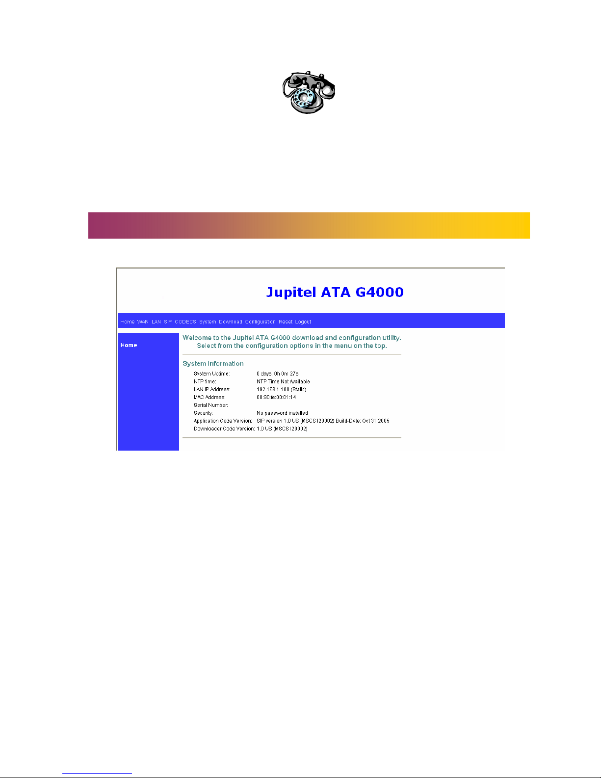
6.1 Home
There are few indicators on the HOME page:-
1. System uptime: Specifies the amount of time system has been up. (Time reset
whenever it rebooted.)
2. LAN IP Address: Indicates the IP address of your LAN.
3. MAC address: MAC address is the address of you MAC.
4. Security: Password which is configured in the “System” section.
5. Application code version: Indicate the version of the application code which
currently in used.
6. Download code version: Indicate the version of the download code which
currently in used.
Settings……………..……...…………………..…………………………….

9
6.2 WAN
6.2.1 WAN Status
In the WAN Status we will able to view the network settings:-
Interface status:
1. Enabled: “Yes – Indicate the WAN is in operating mode.
2. Service: Indicate the system operate either “Routed or bridged” mode.
3. Protocol: The protocol which use for data transferring. (I.e. Ethernet)
4. Interface status: Indicate the WAN status either “Up” or “Down”.
Network settings:
1. Dynamic IP Assignment: “Yes” or “No. Either the host or the user is using DHCP
protocol – Auto Define IP Address
2. IP address: The IP Address for the devices.
3. MAC address: The devices MAC address – actory Define
4. Subnet Mask: Indicates the mask of your IP Address.
5. Default Gateway: The IP address of the gateway. The gateway IP could be
retrieved from DHCP offer in DHCP mode, or be set up manually in fixed IP mode.
6. DNS address: Refers to the address of your dynamic name server, if applicable.
7. VLAN: VLAN tag value encoded in the Ethernet header in all outgoing packets.
8. Priority Tag: priority tag value encoded in the Ethernet header in outgoing
packets.
9. Broadcast Limit& Multicast limit: Please refer to the WAN configuration.

10
6.2.2 WAN Settings
Device operating mode:
1. We can choose either’ Router’ or ‘Bridge’ operating mode.
2. You will check either ‘Obtain WAN configuration dynamically’ or ‘Specify fixed
WAN configuration.’
3. 2 optional operating mode: - ‘Obtain WAN configuration dynamically’, the
information is detected automatically through DHCP or ixed WAN
Configuration – manually set
4. If you choose ‘ Specify fixed WAN configuration’ , you are required to enter
the IP address, subnet mask, IP of the Gateway, and IP of the DNS server, if
applicable.
Multicast limits:
1. Broadcast limit: The value specifies the maximum limit on the percentage of
broadcast packets, which will be bridged to the destination interface (as a
percentage of the source side bandwidth)
2. Multicast limit: The value specifies the maximum limit on the percentage of
multicast packets, which will be bridged to the destination interface (as a
percentage of the source side bandwidth).
Tabla de contenidos


