Johnson Controls WRZ-STR0000-2 Manual de usuario

WRZ-STR0000-2 Series Wireless
Refrigerator or Freezer Temperature
Transmitter and Probe Assemblies
Installation Guide
Application
Use the WRZ-STR0000-2 Series Wireless Refrigerator or Freezer Temperature Transmitter and Probe
Assemblies to sense the temperature in either a refrigerator or freezer unit, and transmit wireless
temperature data to a receiver or controller.
In a mesh application, the WRZ sensor is compatible with the ZFR18xx Wireless Field Bus Systems
(ZFR181x, ZFR182x, ZFR183x). See Table 3. The transmitter communicates with system controllers
through the ZFR18xx Router, the ZFR or the ZFR Pro Series Router. Up to nine WRZ Series Sensors
can associate with a single Controller.
You can also use a WRZ-STR0000-2 Series Wireless Refrigerator or Freezer Temperature Transmitter
and Probe Assembly in a one-to-one application non-mesh network to communicate with a
WRZ-7860-0 Wireless Receiver. The WRZ-7860-0 Receiver transfers data to the controller through
the Sensor Actuator (SA) communication bus. In an application, one WRZ-STR0000-2 Series
Transmitter reports to one WRZ-7860-0 Receiver, but up to five WRZ-STR0000-2 Series Transmitters
can associate with a single WRZ-7860-0 Receiver.
The WRZ-STR0000-2 Series Transmitter can transmit sensed temperature and low battery conditions
to an associated router or receiver. Use the WRZ-STR0000-2 Series Wireless Refrigerator or Freezer
Temperature Transmitter and Probe Assemblies for indoor, intra-building applications only.
Important: The WRZ-STR0000-2 Series Wireless Refrigerator or Freezer Temperature
Transmitter and Probe Assemblies are intended to provide an input to equipment under
normal operating conditions. Where failure or malfunction of the transmitter and probe
assembly could lead to personal injury or property damage to the controlled equipment or
other property, additional precautions must be designed into the control system. Incorporate
and maintain other devices, such as supervisory or alarm systems or safety or limit controls,
intended to warn of or protect against failure or malfunction of the transmitter and probe
assembly.
Important: Le WRZ-STR0000-2 Series Wireless Refrigerator or Freezer Temperature
Transmitter and Probe Assemblies est destiné à transmettre des données entrantes à un
équipement dans des conditions normales de fonctionnement. Lorsqu'une défaillance ou un
dysfonctionnement du transmitter and probe assembly risque de provoquer des blessures
ou d'endommager l'équipement contrôlé ou un autre équipement, la conception du système
de contrôle doit intégrer des dispositifs de protection supplémentaires. Veiller dans ce cas à
intégrer de façon permanente d'autres dispositifs, tels que des systèmes de supervision ou
d'alarme, ou des dispositifs de sécurité ou de limitation, ayant une fonction d'avertissement
ou de protection en cas de défaillance ou de dysfonctionnement du transmitter and probe
assembly.
WRZ-STR0000-2
*241033210J*
Part No. 24-10332-10 Rev. J
2023-05-05

North American emissions compliance
United States
Compliance Statement (Part 15.19)
This device complies with Part 15 of the FCC Rules. Operation is subject to the following two
conditions:
1. This device may not cause harmful interference, and
2. This device must accept any interference received, including interference that may cause
undesired operation.
Warning (Part 15.21)
Changes or modifications not expressly approved by the party responsible for compliance could
void the user’s authority to operate the equipment.
Canada
Industry Canada Statement(s)
The term IC before the certification/registration number only signifies that the Industry Canada
technical specifications were met.
Le terme « IC » précédant le numéro d'accréditation/inscription signifie simplement que le produit
est conforme aux spécifications techniques d'Industry Canada.
Installation
To install the WRZ-STR0000-2 Series Wireless Refrigerator or Freezer Temperature Transmitter and
Probe Assembly, follow these guidelines:
• Transport the transmitter and probe in the original container to minimize vibration and shock
damage.
• Verify that all the parts shipped with the transmitter and probe.
• Do not drop the transmitter or probe, or subject either component to physical shock.
• Do not attempt to remove or repair the circuit board from the transmitter housing. Other than
battery replacement, the transmitter and probe are not user serviceable.
Parts included
The WRZ-STR0000-2 Series Transmitter Assembly ships with the following parts, all factory
assembled:
• WRZ-STR0000-2 Series Transmitter Assembly that includes one transmitter, one mounting base,
and strips of double-sided adhesive foam tape
• Temperature sensor probe assembly that includes one temperature sensor probe encased in a
clear acrylic cylinder, a 9 ft (2.7 m) wire lead, one probe mounting strap, and a strip of double-
sided adhesive foam tape
• One DIP switch overlay for a mesh network application that uses a ZFR or ZFR Pro Series Router
• One DIP switch overlay for a non-mesh network, one-to-one application that uses a WRZ-78x0-0
Receiver
• One installation guide
WRZ-STR0000-2 Series Wireless Refrigerator or Freezer Temperature Transmitter and Probe Assemblies
Installation Guide
2

• Two AA alkaline batteries
Dimensions
See the following figure for features and dimensions of the WRZ-STR0000-2.
Figure 1: WRZ-STR0000-2 features and dimensions, in. (mm)
Callout Description
A Signal test button
B Tamper resistant set screw
C 9 ft (2.7 m) wire lead
D Back of base to front of protrusion
E °F/°C button
Special tools needed
• 1/16 in. (1.6 mm) Allen-head adjustment tool (Johnson Controls® T-4000-119, order separately)
for the tamper-resistant set screw that secures the transmitter to the mounting base.
• Coin to unlock the transmitter housing from the mounting base locking tab.
Mounting
To surface mount the WRZ-STR0000-2 Series Transmitter, use the adhesive tape pieces affixed to
the back of the sensors.
3WRZ-STR0000-2 Series Wireless Refrigerator or Freezer Temperature Transmitter and Probe Assemblies
Installation Guide

Location considerations
Refer to the following sections for information about temperature sensor probe, temperature
transmitter, and wireless transmitter location considerations.
Temperature sensor probe considerations
When you locate the temperature sensor probe, use the following guidelines::
• Mount the probe inside the refrigerator or freezer unit away from the front, to avoid
interference with the stored contents, and to eliminate any false temperature spikes when you
open the door.
• Run the 9 ft (2.7 m) wire lead through the door gap or an existing hole designed for remote
temperature sensor probe installation.
Note: Do not use an existing hole that is designed for electrical voltage, as this affects the
temperature reading. Do not drill a hole through the wall of the refrigerator or freezer unit for
the wire lead unless approved by the refrigerator or freezer manufacturer, and also approved
by the customer.
Temperature transmitter considerations
When you locate the temperature transmitter, use the following guidelines:
• Mount the transmitter on the outside of the refrigerator or freezer unit.
• Mount the transmitter vertically to read the Liquid Crystal Display (LCD) on the face of the unit.
Wireless transmission considerations
To locate the transmitter in wireless applications, use the following guidelines::
• Locate the transmitter on the same building level as the nearest ZFR or ZFR Pro Series Router, or
WRZ-78x0-0 Receiver.
• For best signal transmission, locate the transmitter at least 2 in. (51 mm) away from any metal
obstructions.
• Wherever possible, locate the transmitter in the direct line-of-sight to the ZFR or ZFR Pro Series
Router, or WRZ-78x0-0 Receiver. Signal transmission is best if the path between the transmitter
and the router or receiver is as direct as possible. Line of sight is preferred but not required,
provided no large metal objects block the path.
• Avoid metal obstructions, which includes equipment rooms and elevator shafts, and concrete
or brick walls between the transmitter and the ZFR or ZFR Pro Series Router, or WRZ-78x0-0
Receiver.
• Do not mount the transmitter closer than 2 ft (0.61 m) or farther than 100 ft (30 m) from the ZFR
or ZFR Pro Series Router, or 150 ft (45 m) from the WRZ-78x0-0 Receiver.
• The indoor line-of-sight transmission range between the transmitter and the ZFR or ZFR Pro
Series Router is 50 ft (15 m).
Installing the WRZ-STR0000-0 Series Transmitter
Use the double-sided adhesive foam tape, factory-installed on the back of the device, to surface
mount the WRZ-STR0000-0 Series Transmitter. To mount the transmitter base with adhesive foam
tape, complete the following steps:
1. Clean the required mounting surface to ensure that the adhesive foam tape sticks to the
surface.
WRZ-STR0000-2 Series Wireless Refrigerator or Freezer Temperature Transmitter and Probe Assemblies
Installation Guide
4

Note: The mounting surface, mounting base, and ambient temperature must be at least
50°F (10°C) when mounting the transmitter base with adhesive foam tape.
2. Remove the transmitter housing from its mounting base. See Figure 2.
3. Peel off the protective paper from one side of the factory-installed strips of adhesive foam
tape on the back of the mounting base.
4. When positioned correctly, the arrow between the terminal slots on the inside of the
mounting base points up. Ensure that the mounting base is upright with the tamper-resistant
set screw on top, and press the base firmly onto the clean mounting surface.
5. See Preparing the WRZ-STR0000-0 Series Transmitter for Operation.
Removing a mounting base installed with double-sided
adhesive foam tape
To remove or relocate a transmitter mounted with double-sided adhesive foam tape, complete the
following steps::
1. Remove the transmitter housing from its mounting base. See Figure 2.
Figure 2: Removing the transmitter housing from its mounting base
Callout Description
A Slot
B Tamper-resistant set screw
C Mounting base
D Tabs
E Transmitter housing
a. Loosen but do not remove the tamper-resistant set screw on the locking tab on the
mounting base.
5WRZ-STR0000-2 Series Wireless Refrigerator or Freezer Temperature Transmitter and Probe Assemblies
Installation Guide

b. Insert a coin into the slot in the top of the transmitter housing and depress the locking tab
on the mounting base to release the housing.
c. Swing the transmitter housing off the mounting base
d. Pull the bottom of the transmitter housing down and off the tabs at the bottom of the
mounting base.
e. Reverse these steps to install the housing.
2. To remove the mounting base from the mounting surface, carefully twist the base off of the
surface.
3. Remove the adhesive foam tape from the mounting base and clean the mounting base to
remove any leftover adhesive.
Note: To remount the base on the surface requires new double-sided adhesive foam
tape. Use Can-Do National Tape (Code No. 99116) adhesive foam tape or its equivalent.
Installing the temperature sensor probe
To install the temperature sensor probe, complete the following steps:
1. Peel off the protective paper from one side of the factory-installed strip of adhesive foam
tape on the back of the probe mounting strap.
2. Mount the temperature sensor probe inside the refrigerator or freezer unit away from the
front, to avoid interference with the stored contents and to eliminate any false temperature
spikes when you open the door.
Note: The mounting surface, mounting strap, and ambient temperature must be at least
50°F (10°C) when you mount the temperature sensor probe with adhesive foam tape.
3. Support the wire lead along the inside walls of the refrigerator or freezer unit to the WRZ-
STR0000-2 Series Transmitter, and run the lead through the door gap or an existing hole
designed for remote temperature sensor probe installation.
Note: Do not use an existing hole that is designed for electrical voltage, as this affects
the temperature reading. Do not drill a hole through the wall of the refrigerator
or freezer unit for the wire lead unless it is approved by the refrigerator or freezer
manufacturer, and also approved by the customer.
4. If you use the door gap method for installation, secure the wire lead with tape near where the
lead passes through the door gap to protect it from excessive rubbing or getting caught in
the door hinge.
5. Feed the wire lead through the slot on the bottom edge of the transmitter housing, tie a knot
in the wire just inside the housing to act as a strain relief, and secure the wire ends to the
terminal block as shown in Figure 3.
Important: Do not turn on the WRZ-STR0000-2 Series Transmitter until an installed
receiver or controller operates in the same Radio Frequency (RF) range. Without this
condition, the transmitter uses a higher-than-normal battery current as it attempts to
find a receiver or controller within range, which results in reduced battery life.
WRZ-STR0000-2 Series Wireless Refrigerator or Freezer Temperature Transmitter and Probe Assemblies
Installation Guide
6

Figure 3: Wiring the Temperature Sensor Probe to the WRZ-STR0000-2 Series Transmitter
Preparing the WRZ-STR0000-2 Series Transmitter
for operation
To prepare the WRZ-STR0000-2 Series Transmitter for operation, and to reinstall the transmitter
housing on its mounting base, complete the following steps::
1. Place the appropriate DIP switch overlay, based on the application, over the DIP switches. See
Figure 4 through Figure 6.
Figure 4: Mesh network application DIP switch overlay
7WRZ-STR0000-2 Series Wireless Refrigerator or Freezer Temperature Transmitter and Probe Assemblies
Installation Guide

Figure 5: Non-mesh network, one-to-one application DIP switch overlay
Figure 6: Back of WRZ-STR0000-2 Series transmitter showing DIP switches and batteries
Callout Description
A Place DIP switch overlay here
B Insert two AA alkaline batteries in the battery compartment
2. Set the DIP switches located on the back of the transmitter.
Mesh network
For a mesh network application that uses a ZFR or ZFR Pro Series Router, set the DIP
switches as shown in Figure 4. Refer to the WRZ Series Wireless Room Sensors Installation
Guide (24-10332-2) for information on how to commission multiple WRZ-STR0000-2 Series
Transmitters in a ZFR18xx Series Wireless Field Bus System.
a. Set the POWER switch to OFF.
b. Set the MODE switch to Mesh.
c. Set the PAN OFFSET switches according to the job or system plans.
Important: Ensure that the PAN OFFSET is the same for each ZFR or ZFR Pro Series
Coordinator, ZFR or ZFR Pro Series Router, and WRZ-STR0000-2 Series Transmitter in a
mesh network.
d. Set the ZONE DIP switches to match the Zone Number in the Controller Configuration Tool
(CCT) software. Each Zone Number corresponds to the SA bus address as shown in the
following table.
WRZ-STR0000-2 Series Wireless Refrigerator or Freezer Temperature Transmitter and Probe Assemblies
Installation Guide
8

Table 1: Setting the ZONE DIP switches
Zone number SA bus address
0 199
1 200
2 201
3 202
4 203
5 204
6 205
7 206
8 207
e. Set the MS/TP ADDRESS DIP switches to match the MS/TP address of the controller with
which the transmitter intends to communicate.
f. Set the TRANSMIT LEVEL switch to 10mW.
Non-mesh network
For a non-mesh network, one-to-one application that uses a WRZ-78x0-0 Receiver, set the
DIP switches as shown in Figure 5. Ensure that the AREA and TRANSMITTER ID switches on
the WRZ-78x0-0 Receiver and the WRZ-STR0000-0 Transmitter are set to the same value.
a. Set the POWER switch to OFF.
b. Set the MODE switch to 1 to 1.
c. Set the SENSOR # to 199 for applications with only one transmitter per controller. Use the
other settings for additional transmitters in applications with a single controller. Refer to
the WRZ Series One-to-One Wireless Room Sensing System Technical Bulletin (LIT-12011641)
for information on how to commission multiple WRZ-STR0000-2 Series Transmitters in a
WRZ-78x0-0 One-to-One Wireless Room Temperature Sensing System.
d. Set the AREA switches to match the AREA switch on the WRZ-78x0-0 Receiver.
e. Set the TRANSMITTER ID switches to match the TRANSMITTER ID on the WRZ-78x0-0
Receiver.
3. Install the two supplied AA alkaline batteries into the battery compartment on the back of the
transmitter. Ensure to install the batteries in the correct polarity as shown in Figure 6.
4. If the address DIP switches are set to the correct positions and the temperature sensing
system is ready for operation or testing, set the POWER DIP switch to the ON position as
shown in Figure 4 or Figure 5.
5. Align the tabs on the bottom edge of the transmitter mounting base with the slots on
the bottom edge of the transmitter housing, and rotate the transmitter assembly onto its
mounting base. Reverse the procedure shown in Figure 2.
6. Use a 1/16 in. (1.6 mm) Allen wrench or Johnson Controls T-4000-119 Allen-Head Adjustment
Tool to tighten the tamper-resistant set screw and secure the transmitter assembly onto its
mounting base. See Figure 2.
7. Press and release the signal test button on the WRZ-STR0000-2 Series Transmitter as shown in
Figure 1 to initiate a signal strength test with the associated ZFR or ZFR Pro Series Router, or
WRZ-78x0-0 Receiver. The signal strength is shown on the LCD on the face of the transmitter.
See Figure 7.
9WRZ-STR0000-2 Series Wireless Refrigerator or Freezer Temperature Transmitter and Probe Assemblies
Installation Guide
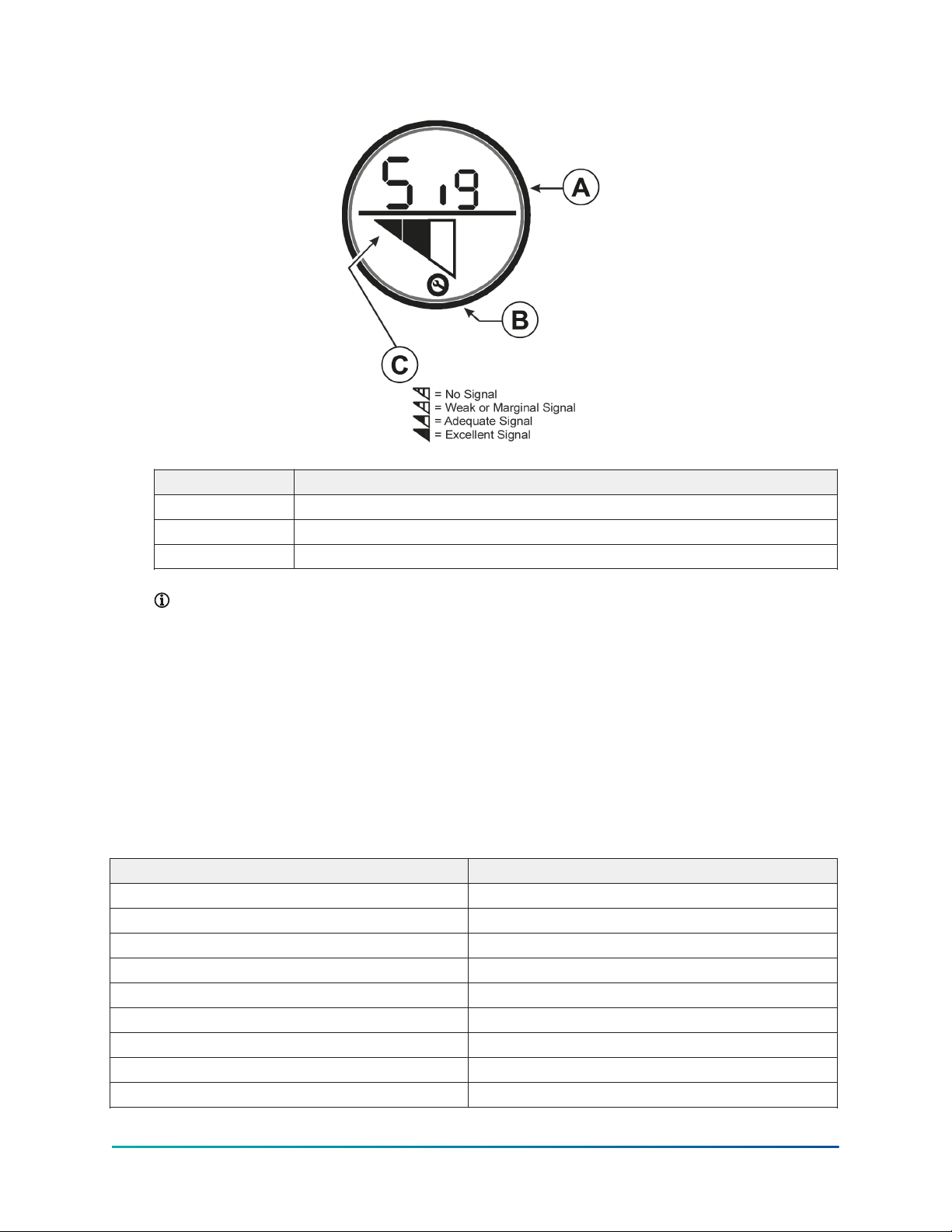
Figure 7: WRZ-STR0000-2 Series Transmitter LCD
Callout Description
A Abbreviation for signal
B Indicates loss of network connection when symbol flashes on
C Signal strength
Note: Use an optional WRZ-SST-110 Wireless Sensing System Tool with the WRZ-
STR0000-2 Series Transmitter as a site survey tool before installation, to determine
potential installation locations for system devices and to determine the wireless signal
strength between the system devices in the application. Refer to the WRZ-SST-110
Wireless Sensing System Tool Installation Guide (Part No. 24-10563-55) for more information
on how to test signal strength.
Additional product information
Table 2 includes Negative Temperature Coefficient (NTC) thermistor sensor temperature and
resistance response characteristics. Use the values in the following table to verify the accuracy of
the temperature sensor in the field.
Table 2: Temperature vs. resistance
Temperature, °F (°C) Resistance, ohms
-30 (-34) 71,246
-20 (-29) 50,127
-10 (-23) 35,756
0 (-18) 25,797
10 (-12) 18,846
20 (-7) 13,924
30 (-1) 10,397
40 (4) 7,846
50 (10) 5,977
WRZ-STR0000-2 Series Wireless Refrigerator or Freezer Temperature Transmitter and Probe Assemblies
Installation Guide
10
Tabla de contenidos


