ivanti ISA8000 Instrucciones de instalación

ISA8000 Hardware Guide

Copyright Notice
This document is provided strictly as a guide. No guarantees can be provided or expected. This
document contains the confidential information and/or proprietary property of Ivanti, Inc. and its
affiliates (referred to collectively as “Ivanti”) and may not be disclosed or copied without prior written
consent of Ivanti.
Ivanti retains the right to make changes to this document or related product specifications and
descriptions, at any time, without notice. Ivanti makes no warranty for the use of this document and
assumes no responsibility for any errors that can appear in the document nor does it make a
commitment to update the information contained herein. For the most current product information,
please visit www.Ivanti.com.
Copyright © 2022, Ivanti, Inc. All rights reserved.
Protected by patents, see https://www.ivanti.com/patents.
Copyright © 2022, Ivanti, Inc. All Rights Reserved. Privacy and Legal.
Page 2 of 65

Contents
Revision History 4
Package Contents 5
System Overview 6
Introduction 6
LED Control Panel 6
Control Panel LEDs 7
Management Port LEDs 8
INT and EXT Port LEDs 9
Air Flow Estimate 9
Air Flow Direction 9
Beeping and Alarms 10
Hardware Specifications 11
System Measurements 11
Power Rating 11
Power Consumption 11
Environmental Requirements 14
Component Specifications 14
Where to Get Replacement Components 14
Console and Initial Configuration 15
Accessing ISA8000 Serial Console through Laptop 15
Accessing ISA8000 Console through Console Server 15
Powering On the System and Selecting the Personality 16
Configuring Basic Settings 17
Setting Up Ivanti Connect Secure Package / Ivanti Policy Secure Package 17
Change the Personality 18
Accessing the Web Admin Interface 20
Licensing the System 20
Installation 21
Preparing for Setup 21
Rack Mounting Instructions 23
Replacing the Power Supply Unit 25
Replacing the Hard Drive 26
Network Cables 34
Standard Warnings and Compliance 36
About Standard Warnings 36
Safety Certifications 36
Electrical Safety 36
General Safety 37
Installation Instructions 40
Circuit Breaker 42
Power Disconnection Warning 44
Equipment Installation 46
Restricted Area 48
Redundant Power Supplies 51
Copyright © 2022, Ivanti, Inc. All Rights Reserved. Privacy and Legal.
Page 3 of 65

Backplane Voltage 53
Comply with Local and National Electrical Codes 55
Product Disposal 57
Power Cable and AC Adapter 59
Certification Statements 63
Revision History
Revision Number and Date Description
1.0, April 2022 Initial release.
1.1, July 2022 Added the following sections:
• Replacing the Power Supply Unit
• Replacing the Hard Drive
Updated the following sections:
• Powering On the System and Selecting the
Personality
• Configuring Basic Settings
Copyright © 2022, Ivanti, Inc. All Rights Reserved. Privacy and Legal.
Page 4 of 65

Package Contents
The ISA8000F/C package typically includes the following:
Item Quantity
Rack Mount Rail Kit 1RU, ISA8000 1
Rail Screw Bag, ISA8000, Mounting Kit 1
Cable, Console, Gray, RJ45 to DB9, 6 ft. 1
Cable Generic, C13, 1 Power Cord 2
Cable, Power, C13/C14, 13A/125V, 1m 2
Packaging box, accessory kit, PSA/ISA 1
Quick Start Guide, ISA8000 1
Copyright © 2022, Ivanti, Inc. All Rights Reserved. Privacy and Legal.
Page 5 of 65
Package Contents
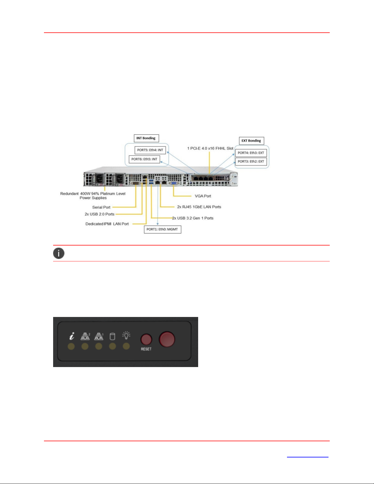
System Overview
Introduction
The ISA8000 features a unique and highly optimized design for low wattage processor platforms. It is
equipped with a high-efficiency low noise power supply. High-performance fans provide ample
optimized cooling.
For added system security, the USB ports have been disabled.
LED Control Panel
The control panel located on the front of the ISA8000 chassis includes power control buttons and status
LEDs. This section describes the LED indicators and the appropriate responses.
Control Panel Buttons
The control panel includes a power on/off button and a reset button.
Copyright © 2022, Ivanti, Inc. All Rights Reserved. Privacy and Legal.
Page 6 of 65
System Overview

Power: The main power switch is used to apply or remove power from the power supply to the server
system. Turning off system power with this button removes the main power but keeps standby power
supplied to the system. Therefore, you must unplug system before servicing.
Reset: The reset button is used to reboot the system.
Control Panel LEDs
The control panel displays five LEDs to monitor the system.
Information LED: Alerts operator of several states, as noted in the table below:
Status Description
Continuously on and
red
An overheat condition has occurred. This may be caused by cable
congestion.
Blinking red (1Hz) Fan failure; check for an inoperative fan.
Blinking red (0.25Hz) Power failure; check for a non-operational power supply.
NIC1 (GLAN1): Associated with the Management port. It indicates network activity when flashing.
Copyright © 2022, Ivanti, Inc. All Rights Reserved. Privacy and Legal.
Page 7 of 65
System Overview

NIC2 (GLAN2): Unused. Will always be off.
HDD: Indicates IDE channel activity or SATA drive activity when flashing.
Power: Indicates power is being supplied to the system power supply. This LED should be illuminated
when the system is operating.
Management Port LEDs
The management port has two LEDs. The yellow LED indicates activity, while the link LED may be green,
amber, or off to indicate the speed of the connection.
LED Color Description
Activity Yellow (flashing) Active
Link Off No connection
Orange 1 Gbps speed
Green 100 Mbps speed
Copyright © 2022, Ivanti, Inc. All Rights Reserved. Privacy and Legal.
Page 8 of 65
System Overview

INT and EXT Port LEDs
Two LAN ports are located on the NIC card. Each Ethernet port has two LEDs.
LED Color Description
Activity Yellow (blinking) LAN Active
Link Off 10 Mbps link speed or no connection
Orange 1 Gbps link speed
Green 10 Gbps link speed
Air Flow Estimate
Equipped Cooling Fan and/or Active CPU Heat
Sink
Estimated
Overall
System Air
Flow Rate
When All
Four
Cooling Fans
Operated at
Full Speed
Six Cooling FANs + 1 passive CPU Heat Sink 52 CFM
Air Flow Direction
The following table gives the air flow direction of the power supply fan and internal CPU fan.
Component Air Flow Direction
Power Supply Fan To the rear of the unit
Copyright © 2022, Ivanti, Inc. All Rights Reserved. Privacy and Legal.
Page 9 of 65
System Overview

Este manual sirve para los siguientes modelos
2
Tabla de contenidos
Otros manuales de Hardware de red de ivanti

Manuales populares de Hardware de red de otras marcas

Matrix Switch Corporation
Matrix Switch Corporation MSC-HD161DEL Manual de usuario

B&B Electronics
B&B Electronics ZXT9-IO-222R2 Manual de usuario

Yudor
Yudor YDS-16 Manual de usuario

D-Link
D-Link ShareCenter DNS-320L Manual de usuario

Samsung
Samsung ES1642dc Instrucciones de uso

Honeywell Home
Honeywell Home LTEM-PV Instrucciones de montaje


