ipf DW34311 Series Manual de usuario

DW34311x
pressure sensor
MANUAL •Subject to alteration! Version: July 2016
ipf electronic gmbh
•Rosmarter Allee 14 •58762 Altena
│
Tel +49 2351 9365-0 •Fax +49 2351 9365-19
│
1

table of contents
safety instructions page 3
controls and indicating elements page 4
description of the operating elements page 5
menu / overview page 6
operation modes of the switching outputs page 8
switch-point with release position page 9
switch-point with hysteresis page 9
window function with switch-point page 10
window function with hysteresis page 10
operating modes page 11
programming page 12
list of parameters page 12
mounting and electrical connection page 15
initial operation / operation page 16
factory settings / technical data page 17
dimensional drawings / list of articles page 18
MANUAL •Subject to alteration! Version: July 2016
ipf electronic gmbh
•Rosmarter Allee 14 •58762 Altena
│
Tel +49 2351 9365-0 •Fax +49 2351 9365-19
│
2

safety instructions
Read the product description before installing the unit. Ensure that the
product is siutable for your application without any restrictions.
Non-adherence to the operating instructions or technical data can lead to
personal injury and/or damage to property.
In all applications check compliance of the product materials (see technical
data) with the media to be measured.
Do never touch the pressure membrane with the fingers or any other object.
The membrane can be damaged irreparably!
Never use these articles in applications where the safety of a person
depends on their functionality!
MANUAL •Subject to alteration! Version: July 2016
ipf electronic gmbh
•Rosmarter Allee 14 •58762 Altena
│
Tel +49 2351 9365-0 •Fax +49 2351 9365-19
│
3

controls and indicating elements
1
2
4
5
6
3
7
1
2
4
5
6
33
7
description function symbol
1 4-digit display displays the current system pressure
parameter, parameter values
265.4
2 LED red
S1
displays the switching state of output 1
lights, if the output is switched -
3 LED red
S2
displays the switching state of output 2
lights, if the output is switched -
4 programming button
Enter/ Set
selection of menus and parameters
setting and saving of parameters
Enter
Set
Enter
Set
5 arrow key
up
setting the parameter values
increasing the value
(fast, keep the button pressed
stepwise by pressing the button short)
6 arrow key
down
setting the parameter values
decreasing the value
(fast, keep the button pressed
stepwise by pressing the button short)
7 ESC finishing programming without saving
key lock: press both the arrow keys at the
same time
ESCESC
MANUAL •Subject to alteration! Version: July 2016
ipf electronic gmbh
•Rosmarter Allee 14 •58762 Altena
│
Tel +49 2351 9365-0 •Fax +49 2351 9365-19
│
4

265.4
265.4265.4
SP.2
description of the operational controls
display
4-digit lighted LED display
symbolic description:
shows the current system pressure (RUN-Mode), menu name, parameters
and parameter values.
blinking display in RUN-Mode: fault report (Error).
3 x blinking in PROGRAMM mode: saving current value after pressing
Enter/Set button.
The indication on the display depends on the programmed function.
If one of these functions is selected in the enhanced Menu, the indication
will be shown on the display.
program button Enter/Set
symbol:
Enter
Set
Enter
Set
Selection of menus and submenus as well as confirming and saving of parameter values.
Short pressing in the RUN-Mode →starting up the base menu.
arrow keys
symbol:
and
Increasing and decreasing the parameter values and scrolling of the menu.
Pressing the button continuously, the value increases or decreases in „fast-forward“
mode. Pushing the button →the value changes step by step.
MANUAL •Subject to alteration! Version: July 2016
ipf electronic gmbh
•Rosmarter Allee 14 •58762 Altena
│
Tel +49 2351 9365-0 •Fax +49 2351 9365-19
│
5

ESC- button
symbol:
ESCESC
Pressing both arrow keys + at the same time results in the ESC function.
With the ESC function you can step backwards inside the menu and parameters
without saving the settings.
In order to leave all menus and submenus please press the ESC-button again and again
until you are back in the RUN-mode.
key lock
If the device is in the RUN-Mode and you press the arrow keys + at the same
time for at least 5 seconds, the key lock will be activated.
The display shows „sLOC“, blinking 3 times.
Now the adjusted settings can be read but not be changed.
For cancelling the key lock please press both arrow keys + for at least 5 seconds
again.
menu / overview
switch-point S1
release position S1 / hysteresis S1
analog output active
error function active
press enter 5sec
advanced functions
press enter , short
switch-point S2
release pos. S2 / hyst. S2
1. level
MANUAL •Subject to alteration! Version: July 2016
ipf electronic gmbh
•Rosmarter Allee 14 •58762 Altena
│
Tel +49 2351 9365-0 •Fax +49 2351 9365-19
│
6

see menu analog
2. level
output 1 configuration
switch-point / release position
switch-point / hysteresis
window function / release position
window function / hysteresis
output 1 off
switching mode S1
switch-on delay S1
switch-off delay S1
output 2 configuration
output 2= S2
output 2= error signal
output 2= analog
output 2 off
switching mode S2
switch-on delay S2
switch-off delay S2
max. peakvalue
= del
e
te
min. peakvalue
= del
e
te
offset setting (± 10%)
dispaly damping (peak-hold-time)
display functions
rotate display
peak-hold
rotate + peak-hold
standard display
Press ENTER for 5s
→
test
-
function
(no timeout)
end of advanced functions
press Enter for at least 5sec, to cause a factory reset
counter switching cycles of S1
MANUAL •Subject to alteration! Version: July 2016
ipf electronic gmbh
•Rosmarter Allee 14 •58762 Altena
│
Tel +49 2351 9365-0 •Fax +49 2351 9365-19
│
7

menu analog ( active only if in OU 2 an analog signal is set)
operation modes of the switching outputs
notes:
•The following examples and descriptions of the switching output 1 (SP1) refer to the
switching function „normally open“ (no). If the switching output 1 is set „normally
closed“ (nc) the states are reversed.
•The minimum range between the switching outputs (SP.1 and rSP.1) is 1% of the
nominal pressure; stated by the system.
•The smallest adjustable hysteresis is 1% of the nominal pressure; stated by the sys-
tem.
•All examples are effective for output 2, if this output is defined as switching output
(SP-2) also.
Ou2= analog output
analog start value
analog end value
damping of the analog output
error–signal for analog output
(in 4 ... 20mA / 20 ... 4mA only)
error–display for analog output
(in 4 ... 20mA / 20 ... 4mA only)
MANUAL •Subject to alteration! Version: July 2016
ipf electronic gmbh
•Rosmarter Allee 14 •58762 Altena
│
Tel +49 2351 9365-0 •Fax +49 2351 9365-19
│
8

output
output
switch-point with release position
programmed parameters: SP.1: 250.0 bar
rP.1: 40.0 bar
An increasing pressure up to SP.1 (e.g. 250bar), switches the output according to the ad-
justed switching function (no or nc). This state remains also for higher pressure.
For decreasing pressure the switching state changes with the pressure value at rP.1 (e.g.
40bar). If SP.1 will be changed, rP.1 remains the same.
The minimum range between SP1 and rSP.1 is 1% of the maximum pressure.
switch-point with hysteresis
programmed parameters: SP.1: 50.0 bar
HYS.1: 20.0 bar
An increasing pressure up to SP.1 (e.g. 50bar) switches the output according to the ad-
justed switching function (no or nc). This state remains also for higher pressure.
For decreasing pressure the switching state changes after passing the hysteresis (e.g.
20bar). If SP.1 will be changed, the hysteresis HYS1 remains the same, that is the release
position is (SP.1 – 20)bar.
pressure [bar]
switch-pointrelease position
switch-point
pressure [bar]
hysteresis HYS1
MANUAL •Subject to alteration! Version: July 2016
ipf electronic gmbh
•Rosmarter Allee 14 •58762 Altena
│
Tel +49 2351 9365-0 •Fax +49 2351 9365-19
│
9
output
output
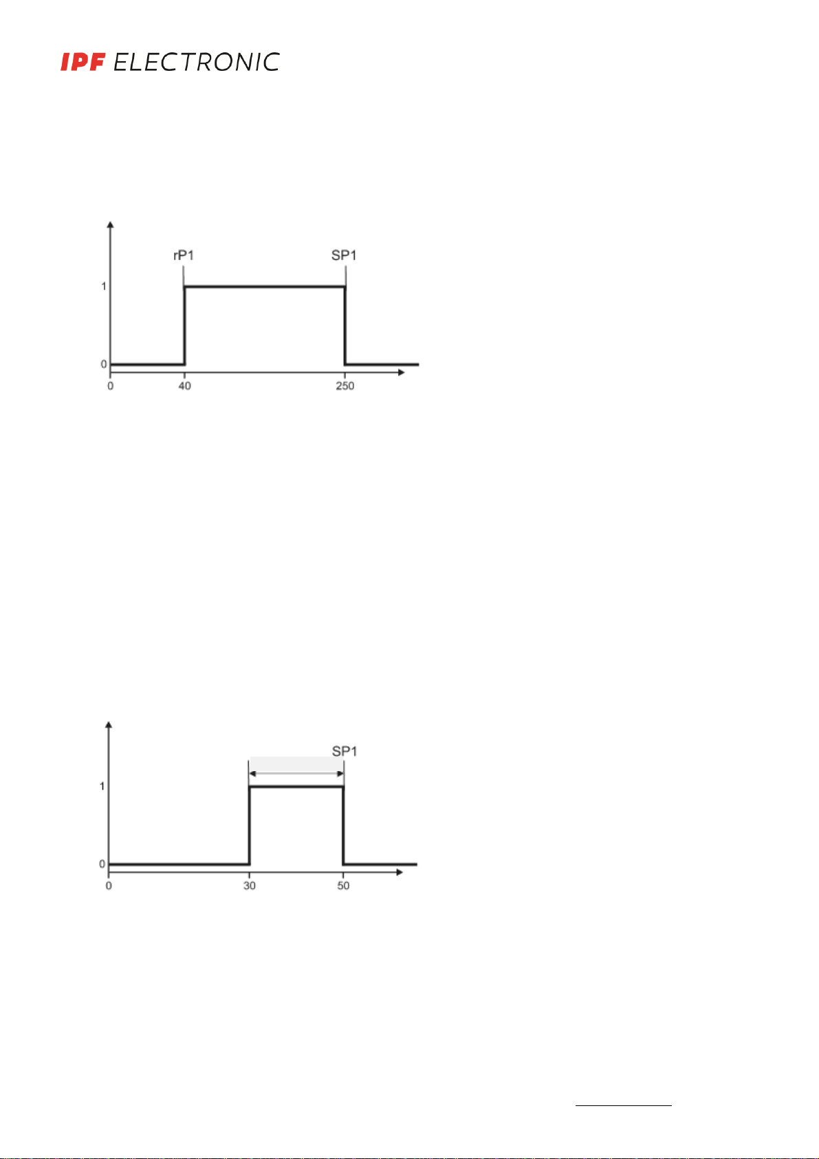
window function with release position
programmed parameters: SP.1: 250.0 bar
rP.1: 40.0 bar
Due to the window function, the monitoring of a defined pressure range is possible.
As soon as the pressure reaches the adjusted range between rP.1 (40bar) and SP.1
(250bar), the output switches according the chosen switching function (no or nc).
The switching state changes if the pressure leaves the adjusted pressure range.
The values for the switch-point and the release position have to be defined separately.
If only SP.1 is changed, rP.1 will remain the same.
window function with hysteresis
programmed parameters: SP.1: 50.0 bar
HYS.1: 20.0 bar
If the pressure hits the adjusted window between (SP.1-HYS.1) and SP.1 (50bar), the
output switches according to the adjusted switching function (no or nc). The switching
function changes when leaving the window. If SP.1 changes, the hysteresis will not
change, e.g. the release position is (SP.1 – 20)bar.
pressure [bar]
switch-pointrelease position
pressure [bar]
switch-point SP1
hysteresis HYS1
MANUAL •Subject to alteration! Version: July 2016
ipf electronic gmbh
•Rosmarter Allee 14 •58762 Altena
│
Tel +49 2351 9365-0 •Fax +49 2351 9365-19
│
10
Este manual sirve para los siguientes modelos
7
Tabla de contenidos
Otros manuales de Accesorios de ipf


