
Interlogix SP1083600 Manual de usuario

SP1083600 Motor-Driven
Blocking Device EasyLock
Installation Manual
EN SP1083600 Motor-Driven Blocking Device EasyLock Installation Manual
DE SP1083600 Motorisches Sperrelement EasyLock –Errichteranleitung
P/N 1078249 (ML) • REV B • ISS 11MAR19

2 SP1083600 Motor-Driven Blocking Device EasyLock Installation Manual
EN: SP1083600 Motor-Driven Blocking
Device EasyLock Installation Manual
Copyright
© 2019 UTC Fire & Security Americas Corporation, Inc. All rights
reserved.
Trademarks and
patents
Interlogix, the SP1083600 Motor-Driven Blocking Device EasyLock
name and logo are trademarks of UTC Fire & Security.
Other trade names used in this document may be trademarks or
registered trademarks of the manufacturers or vendors of the
respective products.
Manufacturer
PLACED ON THE MARKET BY:
UTC Fire & Security Americas Corporation, Inc.
3211 Progress Drive, Lincolnton, NC, 28092, USA
AUTHORIZED EU REPRESENTATIVE:
UTC Fire & Security B.V.
Kelvinstraat 7, 6003 DH Weert, Netherlands
Product warnings and
disclaimers
THESE PRODUCTS ARE INTENDED FOR SALE TO AND
INSTALLATION BY QUALIFIED PROFESSIONALS. UTC FIRE &
SECURITY CANNOT PROVIDE ANY ASSURANCE THAT ANY
PERSON OR ENTITY BUYING ITS PRODUCTS, INCLUDING ANY
“AUTHORIZED DEALER” OR “AUTHORIZED RESELLER”, IS
PROPERLY TRAINED OR EXPERIENCED TO CORRECTLY
INSTALL FIRE AND SECURITY RELATED PRODUCTS.
For more information on warranty disclaimers and product safety
information, please check
https://firesecurityproducts.com/policy/product-warning/ or scan the
QR code.
Certification
European Union
directives
UTC Fire & Security hereby declares that this device is in
compliance with the applicable requirements and provisions of the
Directive 2014/30/EU and/or 2014/35/EU. For more information see
www.utcfireandsecurity.com or www.interlogix.com.
2012/19/EU (WEEE directive): Products marked with this symbol
cannot be disposed of as unsorted municipal waste in the European
Union. For proper recycling, return this product to your local supplier
upon the purchase of equivalent new equipment, or dispose of it at
designated collection points. For more information see:
www.recyclethis.info
Contact information
www.utcfireandsecurity.com or www.interlogix.com
Customer support
www.utcfssecurityproducts.eu

SP1083600 Motor-Driven Blocking Device EasyLock Installation Manual 3
Content
General information 4
Mechanic assembly / Safety 4
Features of the blocking device 4
Additional features with universal connection box 5
Installation 6
Assembly of the blocking device 6
Assembly of the counterpart 7
Emergency opening 8
Switching on 9
Connection to the test device SP1083220 10
Connection 10
Commissioning 12
Troubleshooting 13
Electrical emergency opening 13
Mechanic emergency opening 13
Sluggish bolt 14
Replacing the bolt 15
Product faults 16
Drilling template 16
Specifications 17

4 SP1083600 Motor-Driven Blocking Device EasyLock Installation Manual
General information
The blocking device SP1083600 is designated for the following applications:
•To prevent persons from accessing the armed area of a burglar alarm system
•For access control applications in order to allow access only to authorized
persons
•Other applications, also if they are not in the field of safety (car, furniture, etc.)
Mechanic assembly / Safety
Due to the robust assembly made of plastic, a high reliability and durability of
more than 50 000 cycles is being achieved. If the blocking device fails, there are
electrical and mechanical emergency opening options available.
Features of the blocking device
•VdS class C registered
•Low noise
•Integrated intelligent control
•Little current consumption of less than 50 mA for the locking / opening
process
•Current consumption in rest: <50 µA (also for active entrance)
•Integrated bolt monitoring
•Several closing trials, switching off when blocking
•Can be directly connected to most systems
•The connection is performed using a 4-pin connecting cable:
- Distribution voltage +12 V
- Distribution voltage 0 V
- Entry opened/closed, 0 V: Bolt extends (door locked), open or +12 V: Bolt
moved in
- Exit status opened/closed —active 0 V with blocking bolt moved out
•Drive with statistic signal, several blocking devices are connectable
•Feedback signal of the bolt position
•Easy installation in the door frame. Only the counterpart will be installed to the
door leaf
•Electrical emergency opening via the distribution voltage switching off / on
•Mechanical emergency opening with predetermined breaking point at the bolt
•The locking bolt can be exchanged when it is installed
•Stable plastic construction

SP1083600 Motor-Driven Blocking Device EasyLock Installation Manual 5
Additional features with universal connection box
Since today’s burglary alarm centers possess arbitrarily programmable inputs
and outputs, it is in most cases possible to directly connect this device.
If you cannot realize a direct connection, you can use a universal connecting box
to do so. This way, the following additional features are resulting:
•Can be connected to any EMZ (Alarm System)
•Drive with 0 V or 12 V signals
•Statistic or dynamic drive with one or 2 signals
•Two complementary OC outputs, printed circuit board or if required usable
with pull-up resistance

6 SP1083600 Motor-Driven Blocking Device EasyLock Installation Manual
Installation
The most advantageous installation place is as near as possible to the existing
striking plate of the lock since in this position it will have minimum effects if the
door gets distorted. The blocking device can be installed at any position. The
following devices are required for the installation:
•Wood drill minimum Ø13 mm for the blocking device (optimum Ø13.5 mm to
ease the installation)
•Wood drill Ø13 mm or Ø16 mm for the counterpart
•Assembly aid (adhesive felt) to position the counterpart (is delivered together
with the blocking device)
•Ink pad to color the assembly aid (adhesive felt)
Assembly of the blocking device
Produce a hole with a Ø13.5 mm for the blocking device as well as if necessary
an indentation for the cuff in the door frame. Provide enough space for a cable
loop behind the hole for the blocking device or in the further cable duct so that
sufficient cable reserves are available to extend the blocking device for service
purposes.
The installation direction of the flange should be selected preferably in a way that
the power on the bolt will come from the fixing screws of the blocking device –
also refer to Figure 9 on page 14.
The exact installation dimensions are shown in Figure 1 below as well as in the
drilling template (Figure 11 on page 16).
Optionally, there are an installation housing and a counterpart available to mount
the blocking device.
Figure 1: Assembly of the blocking device
(1) Hole Ø13 for blocking device: Depth about 55 mm
(2) Counter sinking flange: Depth 1.7 mm
(1)
(2)

SP1083600 Motor-Driven Blocking Device EasyLock Installation Manual 7
Cautions
•Clean the hole before installing the blocking device.
•When screwing in the flange fixing screws, pay attention to the position of the
cable so that you will not damage it with the fixing screws.
•When installing the blocking device on an emergency fire door, please check
which structural measures are allowed so that the door will not lose its
certification.
Assembly of the counterpart
The counterpart is assembled in the door leaf. It needs to be assembled in a way
that the locking bolt can extend to the limit stop without contact. The maximum
distance between the flange and the counterpart amounts to 5 mm. This way, it is
guaranteed that the locking bolt will move far enough into the counterpart.
Assembly steps:
1. After having installed the blocking device, connect it to the test device (for the
connection plan, refer to “Connection to SP1083220 test device” on page 10).
After powering (for example, using an accumulator) the blocking device will
open automatically.
2. Glue the assembly aid (adhesive felt) on the locking bolt of the blocking
device and color it using an ink pad.
3. Close the door.
4. Lock the blocking device using the test device. The locking bolt will extend.
After several locking trials the locking bolt will move back since it cannot
reach the end position.
5. Open the locking device by using the test device.
6. Open the door.
7. On the door leaf you can recognize a color circle which shows the exact
position of the counterpart.
8. Mark the center using a center punch and drill the hole according to the
counterpart. For the installation dimensions of the counterparts refer to the
technical data sheet (see also “Specifications” on page 17).
9. Assemble the counterpart.
10.Close the door and perform a functional check using the test device (see also
“Commissioning” on page 12).
Caution: When installing the blocking device on an emergency fire door, please
check which structural measures are allowed so that the door will not lose its
certification.

8 SP1083600 Motor-Driven Blocking Device EasyLock Installation Manual
Emergency opening
Electrical emergency opening
Guide the leads of the distribution voltage to a place which is accessible in case
of a failure (for example, behind the bell or the cover of the communicator, or
others) in order to be able to use the electrical emergency opening options. By
shortly powering down and up the distribution voltage the bolt will be moved in —
also if the entrance is set to “Closed“. Only after switching over the entry from
“Opened”to “Closed”the bolt will be extended again.

SP1083600 Motor-Driven Blocking Device EasyLock Installation Manual 9
Switching on
The switching on is performed via a 4-pin cable. Two leads are required for the
power supply —nominal 12 VDC. The drive is performed with a static signal 0 V
—active. Additionally an open connector output is available, which switches
approach to 0 V if the locking bolt is extended.
Figure 2: Blocking device connections
Table 1: Inputs and outputs of the blocking device
Signal
Lead color
Description
+12 V
White
Power supply +12 V
0 V
Brown
Power supply 0 V
Input
Green
Input “Closed“
- 0 V = “Closed”
- open or +12 V = “Opened”
Output
Yellow
Open collector output, active 0 V: Display of the status “closed”
10 SP1083600 Motor-Driven Blocking Device EasyLock Installation Manual
Connection to SP1083220 test device
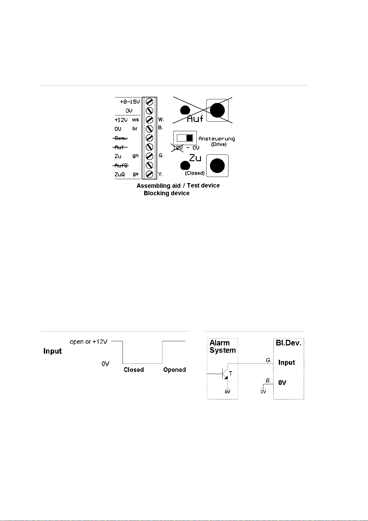
During the commissioning and for further test purposes you can use SP1083220
test device. For the connection refer to Figure 3 below.
Figure 3: Connection to SP1083220 test device
Connection
To connect the blocking device you can use the armed or not armed output of a
burglary alarm system or a timely limited release signal for the entrance control
applications.
When activating the input, the blocking device closes; when deactivating, the
blocking device opens.
Signal behavior and example for switching on with “0 V-activated”—
“armed” signal
Figure 4: Input voltage behavior
Figure 5: Ext. armed 0 V —active
The input of the blocking device requires very little current –average 3 to 4 µA. If
the control output, which activates the input, has a residual current of few µA (for
example, due to the corresponding burglary alarm center protective circuit –
varistors, TVS diodes, etc), it may occur that the blocking device will not correctly
react when changing over the output from “active“ to "inactive“. In order to work
properly, a pull-up resistance can be put between the input and +12 V. The
resistance value should not exceed 1 MΩ.
SP1083600
Tabla de contenidos
Idiomas:


