
Interfire A1000.2 Manual de usuario

2 CHANNEL / 4 CHANNEL / 5 CHANNEL
AUTOMOTIVE AMPLIFIER
INSTRUCTION MANUAL
A300.2 / A500.2 / A700.2
A1000.2 / A1100.2 / A2200.2
A500.4 / A700.4 / A900.4 / A800.5
1
free installation.
• Four Class''AB'' High-Current DualDiscrete Drive Stages.
• Class ''AB''Technology MOSFET PWM Power Supply.
• Bridgeable &TRI-Mode Operation.
• Continuously Variable 12dB/Octave HighPass & 12dB
/Octave Low PassCrossover.
• Subwoofer Variable Crossover forDeep Bass Control.
• Enhanced BassBoost +12dB @50Hz.
• Silver PlatedRCA, Power & Speaker Terminal.
• Soft Start& Muting.
• Overload, Thermal and ShortCircuit Protection.
• Power &Protection indicator.
• Bass LevelRemote Control(16.4Fit) -A1100.2 /A2200.2
Your new high fidelity bridgeable/stereo amplifier is designed to deliver maximum enjoy
ment and oneyear of troublefree service. Pleasetake a fewmoments to readthis manual
thoroughly. It will explain the features and operation of your unit and help insure trouble
authorized installer. It's your car!
• If afterreading the directionsyou feel uncomfortableabout installing theamplifier in your
car, or not equipped or competent to do so, you should have the amplifier installed by an
• Negative battery terminal must be disconnected before any electrical connections are made.
• Be surechoose a locationthat provides substantialventilation for theamplifier. The most
preferred locations would be in your car's trunk, under the front seats or on the back wall
of a truck.
• The location chosen should provide at least 2" of clearance above the amplifier for adequate
ventilation.
• If the amplifier is to be mounted vertically be sure that it is in a place where adequate air
will flow alongthe length ofits heatsink finsfor cooling.
• NEVERmount theamplifier upside down, this willcause the heat torise back into the
amplifier causing thermalshutdown or possiblepermanent damage.
• NEVER mount the amplifier in a location that issubject to direct sunlight or exposed to
moisture.
• Be sureto mount theamplifier to astrong, solid surfacewhich will notgive way under the
stress of asudden stop oraccident.
• Make sure that the mounting screws will not penetrate the gas tank, brake and fuel lines,
wiring or othercritical parts ofyour car wheninstalled.

• NEVER operate the amplifier without the proper power and ground wire, 10 gauge minimum.
• NEVER operate the amplifier without proper fusing. Fuse holder must be located with in
0.5 meters from the battery. This fuse is to protect the car not the electronics. In case of a
short, the fuse will blow instead of the wire burning up. Using other than the recommended
fuse ratings at the battery and at the amplifier may cause damage to the amplifier and will
• Do not run wiring underneath or outside the car since exposure to the elements may cause
the insulation to deteriorate rapidly, resulting in short-circuits and/or intermittent operation.
• To help minimize interference, it is best to run the power cables along the opposite side
.
• Whenever wires pass through metal, rubber or plastic grommets must be used to prevent
• Whenever possible, use cable ties, mounting clamps and similar wiring aids. (available
from an electrical supply or auto parts store) Adding stress relief loops to wiring is also
• It is best to test the system before the amplifier is mounted and interior of car is reassembled.
• If the temperature inside your car reaches extreme levels(such as sitting locked up for
several hours in the hot sun or exposed to a very cold winter's day)the amplifier may go
into protection mode and shut off. Leave the unit off until the ambient temperature returns
• The amplifier operates with any vehicle using a 12 volt negative ground system. If you are
not sure of the type of electrical system in your vehicle, consult your authorized dealer or
• NEVER ground the speaker leads and NEVER allow the speaker leads to come in contact
• Remote turn on wire must be switched by the radio does not have a remote turn on or
antenna output, connect to wire that has a positive 12 volts when the key is turned to the
• Do not listen to high volumes for extended periods of time or hearing damage may occur.
2
void your warranty.
all cables should be run beneath carpets and inside trim pieces.
from the audio cables
the metal from wearing through the installation and causing a short.
advisable to prevent straining or breakage.
to normal.
qualified mechanic.
with each other. Speaker wire should be 18 gauge or larger.
accessory. If the amplifier does not turn off the battery will die.

1. After reading precaution, decide where you are going to install the unit. Also, see Fig.1.
2. Once thelocation has beendetermined, place theamplifier into position.Using a felttip
pen or pencil mark the four holes to be drilled for mounting. NEVER use the amplifier as
a template for drilling. It is very easy to damage the amplifier surface in this manner.
3. Remove amplifier. Drill four 3.5 m/m holes into mounting surface. If you want to mount
4. If possible, test the system to ensure it is operating correctly before final mounting of
5.
FIG.1
3
Self Tapping Screws
MOUNTING:
Mount the amplifierusing the supplied4 self tappingscrews.
the amplifier to MDF or wood panel, drill four 3.0m/m diameter holes into mounting surface.
the amplifier.

It is important to have good quality power and ground connections. Remember, to complete
an electrical circuit, the ground connection is just as important as the positive power
connection. Before any power connections are made, disconnect the ground cable at the
When the power supply lead, memory backup lead or ground lead are extended use a 5mm²
(AWG5) or larger automotive grade cable which will withstand friction and heat to safe
GND = Connect the proper gauge ground wire to the amplifier "GND" terminal. Locate the
position on the chassis of the car to which the amplifier is to be grounded. The surface must
be free from any paint or dirt. This can be accomplished with a small grinding bit, sand
paper or wire wheel. NOTE: Do not ground the amplifier to the "frame of the car. The frame
on most cars and trucks is not grounded to the chassis(body). Use Solder or a clamp ring to
connect the ground wire. Pre-drill the prepped chassis to bolt the ground ring terminal with
nut, bolt and lock washers. Insulate metal and connector with paint or silicon to prevent
rust and oxidation. Silicon also works great to prevent nuts and bolts from working loose in
a harsh environment of an automobile. Upon completion of the ground connection, grab
wire or connector and confirm that it is a solid connection. To prevent engine noise, it is
REM = Connect the remote wire (power antenna output) from the head unit to the remote
turn-on wire of the amplifier. If the head unit is not equipped with a remote/antenna output,
locate a wire that is controlled by the accessory position of the key. It is important to have
the amplifier turn off with the radio or key. If the amplifier remains on, the result will most
12V = Connect the proper gauge power wire to the amplifier "B+" terminal. Run wire to
wards the fuse holder that is no greater then 0.5 meters from the battery. Remember, the
fuse is to protect the safety of the car in the case of a short. Connect fuse holder to battery,
4
This amplifier will accept low level inputs only. Low level is the same as line level. The low
level signal is carried through RCA cables. It is preferred to use low level inputs to the amplifier
if the head unit is equipped with the low level outputs. If not, you can use a "high to low
Connect the low level/line level RCA cables from the head unit, or signal processor, to the
converter" available throughyour local caraudio shop.
line level inputon the amplifier. See Fig.2 system wiring diagrams.
battery.
grade against fires occurring as a result of short-circuiting.
recommended to ground the head unit and other audio electronics in the same location.
likely be a dead battery.
but do not install fuse at this time.

5
FIG.2
+12V REM GND
AUTO - ANTENNA LEAD
CH1 CH2
CAR STEREO HEAD UNIT
LINE INPUT
GAIN BASS L.P.F
L.P.F
H.P.F
H.P.F
6V 0.2V 0dB 12dB 50Hz 250Hz
FLAT
80Hz 1.2KHz
CROSSOVER
CH1
CH2

6
CH3 CH4CH2CH1
+12V REM GND
AUTO - ANTENNA LEAD
CAR STEREO HEAD UNIT
FIG.2
LINE INPUT LINE INPUT
GAIN GAINBASS BASS
CROSSOVER CROSSOVER
6V 0.2V 0dB 12dB 50Hz 500Hz
FLAT
L.P.F H.P.F
FLAT
L.P.F H.P.F
CH1
CH2
CH3
CH4
50Hz 500Hz 0dB 12dB 6V 0.2V
CH 1/2 CH 3/4

7
CH3 CH4CH2CH1 CH5 CH6
+12V REM GND
AUTO - ANTENNA LEAD
CAR STEREO HEAD UNIT
FIG.2
6V 0.2V FLAT
L.P.F
250Hz50Hz 1.2kHz80Hz 1.2kHz80Hz 250Hz50Hz
H.P.F
GAIN
CH 1/2
LINE INPUT
GAIN L.P.F L.P.FH.P.F H.P.F
FLAT
LINE INPUT
CH1
CH2
CH3
CH4
CROSSOVER CROSSOVER
6V 0.2V FLAT
250Hz50Hz 1.2kHz80Hz 6V 0.2V
CH5
CH6
CH 5
CH 3/4
POWER
B+GND REM
FUSE
SPEAKER
CH1
(+) (+)
ON
PROTECT
BRIDGED
CH2
POWER
B+GND REM
FUSE
SPEAKER
CH1
(+) (+)
ON
PROTECT
BRIDGED
CH2
POWER
B+GND REM
FUSE
SPEAKER
CH1
(+) (+)
ON
PROTECT
BRIDGED
CH2
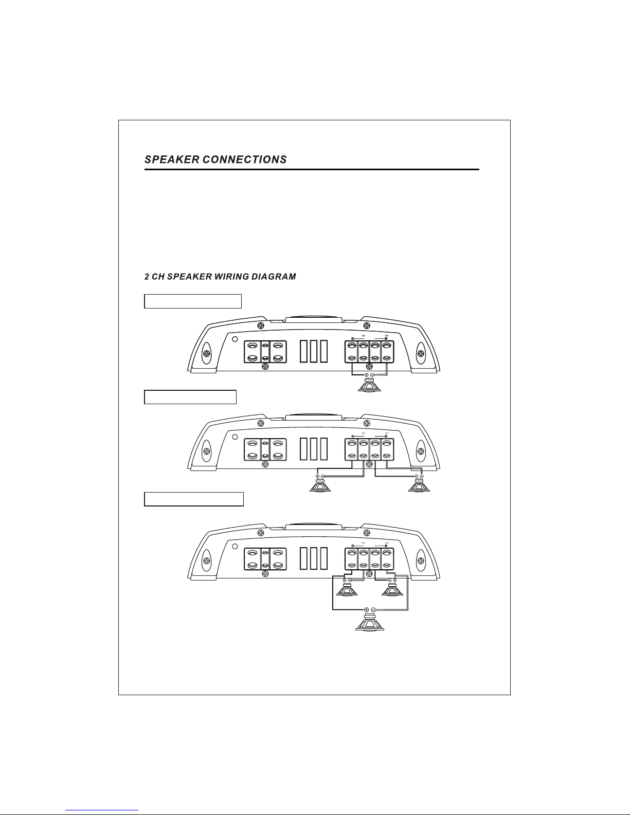
This amplifier can operate in one, two or three channel mode. The minimum impedance for
single channel (bridged/mono) operation is 4 or 8 ohms. Tri channel power is referred to
stereo and mono at the same time. Minimum impedance remains the same for three channel
(front /subwoofer) systems as long as proper passive crossovers are used. Connect right
and left speaker wire to corresponding speaker output terminals of the amplifier. Be sure to
have the positive wire from the speaker connected to the positive speaker terminal of the
amplifier and the negative wire from the speaker must connect with the negative speaker
terminal of the amplifier. Reversing any of these connections will result in the speaker cones
moving out of phase which causes bass cancellation. See Fig.3 Speaker Output Connections.
2 - 4 Ohm
1 CH 2 CH
WOOFER 2CH+1CH
4 - 8 Ohm
2 CH
3 CH
1 CH
4 - 8 Ohm
1 SPEAKER BRIDGED
2 SPEAKER STEREO
3 SPEAKER TRI MODE
8
4 - 8 Ohm
1CH
FIG.3
POWER
B+GND REM
FUSE
SPEAKER
L R
(+) (+)
ON
PROTECT
BRIDGED

CH2
POWER
B+GND REM
FUSE
SPEAKER
(+) (+) (+) (+) CH4CH3
ON
PROTECT
CH1
BRIDGED BRIDGED
2 SPEAKER BRIDGED
2 SPEAKER + 1 SUBWOOFER
4 SPEAKER STEREO
6 SPEAKER HEX MODE
9
2-4 Ohms
4 CH
5 CH
4-8 Ohms
6 CH
4-8 Ohms
FIG.3
CH2
POWER
B+GND REM
FUSE
SPEAKER
(+) (+) (+) (+) CH4CH3
ON
PROTECT
CH1
BRIDGED BRIDGED
3 CH
SUB WOOFER
4-8 Ohms
2 CH1CH
2-4 Ohms
CH2
POWER
B+GND REM
FUSE
SPEAKER
(+) (+) (+) (+) CH4CH3
ON
PROTECT
CH1
BRIDGED BRIDGED
3 CH2 CH1CH
2-4 Ohms
4 CH
CH2
POWER
B+GND REM
FUSE
SPEAKER
(+) (+) (+) (+) CH4CH3
ON
PROTECT
CH1
BRIDGED BRIDGED
3 CH
2 CH
1CH
4-8 Ohms
4-8 Ohms
1 CH 2 CH
4-8 Ohms
Este manual sirve para los siguientes modelos
9
Otros manuales de Amplificador de coche de Interfire


