Intel FALCON 8+ Manual de usuario

INTEL® FALCON™ 8+
Unmanned Aircraft System
QUICK START GUIDE

QUICK START GUIDE – Rev. 06 July 2017 QUICK START GUIDE – Rev. 06 July 2017
2
GloSSARy
• UAV: Intel® Falcon™ 8+ Unmanned Aerial Vehicle (UAV) –
includes all ying parts
• CTR: Intel® Cockpit Controller – ground control station
• BMS: Intel® Powerpack Battery Management System –
smart battery
• UAS: Intel® Falcon™ 8+ System / Intel® Falcon™ 8+
Unmanned Aircraft System (UAS) – Product including UAV
and all dedicated accessories
• Payload: Camera mount with gimbal and camera
InTEnDED USE
This Product is a UAS that is intended for commercial use only,
such as for visual inspection, mapping and surveying. It is
not intended for any consumer or recreational use.
You must read, understand, and follow all documentation
before using the UAS.
DISClAImER
The features and benets of the UAS depend on its
conguration and may require enabled hardware,
software, or service activation. Technical results may have
been estimated or simulated, using internal analysis, or
architecture simulation, or modeling of Intel Corporation,
or Ascending Technologies GmbH, acquired by Intel
Corporation and merged into Intel Deutschland GmbH, and
provided to you for informational purposes. Any dierences
in your UAS hardware, software or conguration may aect
actual performance.
SAfETySymbolS USEDInThEQSG
Critical Warning: Indicates important information that
can be ight critical.
General Information: Shows information helpful in
operating and using the UAS.
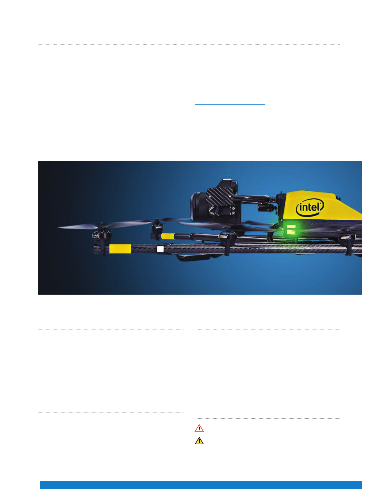
ThAnKyoUfoRPURChASInGThEInTEl®fAlCon™8+UnmAnnEDAIRCRAfTSySTEm
Congratulations on your new Intel® Falcon™ 8+ Unmanned
Aircraft System (UAS).
This UAS is purposely built for professional use. It is not
intended for consumer use. You should already have
experience ying a UAS, which requires control of the drone
with a ground control station similar to the one included with
the Intel® Falcon™ 8+ UAS.
This Quick Start Guide (QSG) presents a brief summary of
the UAS, how to set it up and steps to get started. The QSG
consists of the following main sections:
• UAS Description: Packing list, UAS components, ground
control station, payloads, etc.
• Operating the UAS: Safety precautions, pre-ight and
post-ight checks, and steps to get started – preparing,
using and controlling the UAS.
Before using the UAS, please read the Terms and
Conditions of Use, and Safety Warnings enclosed with this
package. It is important that you also read the User Manual
before using the UAS. Download the User Manual at
www.intel.com/Falconmanual .
In addition, Intel strongly recommends that you attend a
pilot training before you use the UAS. For further details
on training, contact the reseller from whom you bought the
UAS, or if you bought the UAS directly from Intel, contact
Intel.

QUICK START GUIDE – Rev. 06 July 2017 QUICK START GUIDE – Rev. 06 July 2017
3
SAfETyGUIDElInES
These guidelines must be read, understood, accepted and followed by any personnel who operate the UAS:
Do’s:
• Comply with all laws and regulations. You are responsible for knowing and complying with all laws and
regulations applicable to the airspace in which you operate.
• Professional drone operators must comply with all applicable insurance, and aviation-specic liability
requirements.
• Conduct the “UAS and safety check”, “pre-ight” and “post-ight” checks according to the User Manual.
• Maintain the UAS in a safe and airworthy condition.
• Use your best judgment, and prioritize the safety of the environment in which you are ying, and the
people and objects within it.
• Fly at a safe distance and/or wear appropriate safety equipment.
• Intensive training of every pilot, to operate the UAS in all ight modes, is mandatory.
• Fly in dry conditions only - the UAS and payloads are not waterproof.
• Operate the UAS only within the specied operational limits.
Don’ts:
• Do not disassemble the UAS.
• Do not transport the UAS in containers not approved by Intel Corporation.
• Do not operate the UAS under the inuence of alcohol or drugs.
• Do not make any unapproved modication to the UAS.
• Do not y beyond the line of sight.
• Do not y in closed or restricted areas.
• Do not y at temperatures below -5° C (23° F) or above +40° C (104° F).
• Do not exceed speed of 16 m/s in Height-Mode or descend faster than 10 m/s in Manual-Mode.
• Do not y in problematic environments with high electromagnetic disturbances.
• Do not operate the UAV in potentially explosive environments.
UAS DESCRIPTIon
What’s Inside the Package?
When you unpack your Intel Falcon 8+ UAS for the rst time, please make sure that all the items, which you specied
in your purchase order, are included.
Make sure the items are not damaged from shipment. If any of the items are missing or damaged, contact your dealer
or contact the technical support team at Intel.
Violation of these safety guidelines might be illegal and
subject to ne, and will result in the loss of warranty.

QUICK START GUIDE – Rev. 06 July 2017 QUICK START GUIDE – Rev. 06 July 2017
4
Intel Falcon 8+ UAS Case**
This case is used for all necessary parts of your Intel Falcon 8+ UAS.
Intel Cockpit Controller Case**
Following the numbers, the slots contain:
Intel Falcon 8+ UAV without payload and batteries
Power supply units for charging the Intel Powerpack Batteries
(optional) (6)
Space for accessories, e.g. sun glasses
Toolkit with spare propellers (see Figure 02 below)
Space for the payload when mounted directly onto the UAV.
(For load security you must take the foam bolster inlet, which is
supplied with the payload case.)
Space for Intel Powerpack Batteries (shipped separately)
Space for Independent Camera Control (ICC) gamepad
(optional)
Space for extra equipment, if any, which is not part of the UAS,
e.g. reective safety vest or video goggles
1
2
3
4
5
6
7
8
Figure 01
1
2
2
34
5
67
8
Toolkit and spare parts
Figure 02
Intel Cockpit Controller with mounted sun shield (for transporting
the Intel Cockpit Controller in the case, the sunshade should be
arranged as shown to provide extra protection of the touchscreen
tablet against scratches during transportation.)
Additional space to store extra items, e.g. an extra power
supply
Included in the case, but not shown:
Shoulder harness, located underneath the sun shield protected
touchscreen tablet.
1
2
1
2
2
Figure 03

QUICK START GUIDE – Rev. 06 July 2017 QUICK START GUIDE – Rev. 06 July 2017
5
Main Components
The UAS comes with the below main components:
•The Intel Falcon 8+ UAV
• The Intel Cockpit Controller
• The Intel Powerpack Batteries
• Payload
The payload of the Intel Falcon 8+ UAS must be placed as
shown in Figure 04. Make sure that it is placed conveniently
inside the foam bolster.
The foam bolster cover (not shown) located on top of the
payload, should be used to secure the payload when it is
transported in the Intel Falcon 8+ UAS case, while it is mounted
onto the UAV.
** The images of the items above are for illustration purpose only, and the actual item(s) packed with your Intel Falcon 8+ UAS may dier from the one(s) depicted
here depending on, for example, which payload you ordered.
1
2
2
3
4 4
4 4 UAV with payload – top view:
Actively stabilized camera mount with gimbal and camera
Motor rails
Central unit
Carbon cross
1
2
3
4
Payload Case**
The Intel Falcon 8+ UAV
Figure 04
Figure 05

QUICK START GUIDE – Rev. 06 July 2017 QUICK START GUIDE – Rev. 06 July 2017
6
2
2
1
3
5
5
4
4
UAV – back view:
Carbon ber chassis
USB stick slot (supports up to 16 GB, le system: FAT32,
allocation unit size: 32 kilobytes)
Hole for camera mount carbon rod and knurled securing nut
(see no. 5 in Figure 11)
Battery compartments with retaining clips (7) for batteries
Power button
Micro SD-card slot (SD-card: speed class 10 minimum,
supports up to 16 GB, le system: FAT32, allocation unit size:
32 kilobytes); for ight logs (black box)
Battery marks
Built inside:
Electronics for ight stabilization and power supply
Diversity data link modules
Video transmitter module
Carbon cross with center cross piece, antenna arrangement:
Data link antennas (2.4 GHz) and video link antennas (5.8
GHz) are integrated into the landing feet. They are diagonally
arranged as shown in Figure 07.
1
2
3
4
UAV with payload – bottom view:
Payload
Motor rails
Center cross piece
Carbon cross
Landing feet
1
2
3
4
5
5
6
7
Figure 07
Figure 08
1
3
5
62
77
44
Video
Video
Data
Data
Figure 06

QUICK START GUIDE – Rev. 06 July 2017 QUICK START GUIDE – Rev. 06 July 2017
7
UAV – front view:
Hole for camera mount’s carbon rod
Connector slot for payload adapter plug (see no. 2 in
Figure 25)
Retaining clip for payload adapter
Cable tube containing cabling of antennas (for example)
Fan for internal cooling behind slots
Vibration dampers
Motor rails and related elements consist of:
Propellers (mounted directly on motors)
Brushless motors (mounted directly on mounts)
Brushless motor mount
Carbon ber tube
Connector between carbon cross and motor rails
Landing foot
UAV – side view:
LED position light
Vibration dampers
Cable tube
Each motor rail consists of four brushless motor controllers,
seated within the carbon tube.
1
1
1
2
2
2
3
3
3
4
4
5
5
6
6
Figure 09
Figure 10
13
2
5
66
4
66
3
1
22
1
1
2
2
3
3
45
6
Figure 11

QUICK START GUIDE – Rev. 06 July 2017 QUICK START GUIDE – Rev. 06 July 2017
8
Payload
Overview of the Intel Cockpit Controller
The Intel Cockpit Controller
The payload consists of:
Actively stabilized payload with circuitry for controlling camera
Camera (e. g. Sony Alpha 7R*)
Pitch Servo
Lightweight Carbon Fiber Structure
Knurled Securing Nut for the Camera Mount
Payload Adapter
Controller – top view, with unfolded antenna panel:
Control Unit
Touchscreen Tablet with Preview Video (optional with sun
shield)
Antenna Panel, Unfolded (2.4 GHz data link and 5.8 GHz video
link antennas)
Controller – right side view:
Control Unit
Touchscreen Tablet with Preview Video (optional with sun
shield)
Antenna Panel, Unfolded (2.4 GHz data link and 5.8 GHz video
link antennas)
1
1
1
2
2
2
3
3
3
4
5
6
12
3
4
5
6
The Intel Cockpit Controller is the main control hub for the Intel Falcon 8+ UAV, and the attached payloads. It is designed to
be carried and operated by one person, and displays all relevant ight information.
The communication between the Intel Cockpit Controller, and the Intel Falcon 8+ UAV, is realized by two independent 2.4
GHz digital data links. The preview video is transmitted digitally on 5.8 GHz. The Intel Cockpit Controller uses the same
battery type as the Intel Falcon 8+ UAV. The battery is located in the battery compartment, which can be accessed from the
bottom of the Intel Cockpit Controller.
Figure 12
Figure 13
Figure 14
1
2
3
1
2
3

QUICK START GUIDE – Rev. 06 July 2017 QUICK START GUIDE – Rev. 06 July 2017
9
There are dierent connectors on the back of the controller:
4 X USB
1 X HDMI*
The USB port, labeled USB 1, can only be used to perform Intel
Cockpit Controller rmware updates from a USB stick.
The other USB ports can be used to connect the ICC, or USB
sticks with pre-planned ight missions to be imported.
A sun shield can be attached to the touchscreen tablet to avoid
reections. It is foldable for storage and transport.
Figure 15
The functional elements of the controller are:
Start/Stop Button (starts/stops the motors when the left stick
is simultaneously held down at minimum)
GPS (GPS-Mode ON)
HGT (Height-Mode ON) when both buttons are switched ON/lit,
then Manual-Mode is activated
Left Rocker Switch (R1) (controls the camera pitch angle)
Right Rocker Switch (R2) (controls dierent camera functions
depending on the attached payload)
Left and Right Control Sticks
Status Display
Left Push Button (B1) (sets the camera to predened angles
+/-90°, +/-45° and 0° - see "Setting the Camera Angle" section
for details)
Right Push Button (B2) (controls dierent camera functions
depending on the attached payload)
4 Function Buttons for Status Display
Return to Home Button
Power Button
Integrated Shoulder Harness Holders
1
2
3
4
4
5
6
7
7
8
9
10
11
12
44
55
6
77
9
10
3
Figure 16
Figure 17
11
8

QUICK START GUIDE – Rev. 06 July 2017 QUICK START GUIDE – Rev. 06 July 2017
10
Figure 18
Figure 19
Figure 20
Headphone port (mini-jack): Located on the lower right side of
the Intel Cockpit Controller to connect headphones, which may
be helpful under noisy conditions.
Small loudspeaker: Plays back acoustic warnings inside the
Intel Cockpit Controller when headphones are not connected.
1
2
Battery compartment with magnetic lid: Located on the lower
left of the Intel Cockpit Controller.
Overview of the Status Display
Touchscreen Tablet
The Status Display shows all relevant information for ying. It is built into the Intel Cockpit Controller control unit.
The touchscreen tablet is directly mounted onto the remote unit of the Intel Cockpit Controller, and cannot be removed. It is
powered by the battery of the Intel Cockpit Controller.
The touchscreen tablet serves as a video monitor, displays ight information, and gives access to extended functionality.
Via the Status Display, you can view the current settings, and
adjust specic functions of the UAV. To do so, use the four
buttons under the lower left corner of the Status Display.
Escape (left side) is used to leave menus/submenus, and
to clear functions. In the following text it is displayed as
ESC.
With the Left arrow button (middle, left side) and the
Right arrow button (middle, right side), you can scroll
through menus or alter parameters.
Enter (right side) is used to enter menus and activate
functions. In the following text it is displayed as ENT.
1
1
2
1
Otros manuales para FALCON 8+
5
Tabla de contenidos


