Integral Audio 1100S Manual de usuario

IMPORTANT
!
• ReadthisInstallationGuideCarefullyandCompletelybeforeproceeding.
• DisconnectNegativeBatteryTerminalbeforebeginningwork.
• Thisisaguide–yourvehiclemayvary.ALWAYScheckbehindpanels,
etc.beforedrillingorscrewingintoanypartofavehicle.
• Youareresponsibleforyourownvehicle–useyourbrainandbecareful!
35
INSTALLATION
DIFFICULTY
OUT OF
INSTALLATION GUIDE
MINI Cooper Hardtop 2007+ (R56)
Model 1100S Subwoofer System
TheMC1100SSubwooferenclosureinstallsinthe
flooroftheluggagecompartment(boot).Theampli-
fierinstallsbehindthetrimpanelontherightsideof
theboot.
VehiclesequippedwiththeDigitalTuneroptionwill
needtoinstalltheamplifierunderthefrontseat(con-
tactusformoreinfo).
Contents
WHAT’SINCLUDED&WHATYOUWILLNEED...................................2
INSTALLATION:
A.PREPTHEVEHICLE....................................................................3
B.RUNTHEPOWER&GROUNDWIRES.......................................3
C.SIGNALWIRING(BASESTEREO)..............................................5
D.SIGNALWIRING(HIFI).................................................................6
E.AMPLIFIERMOUNTING&CONNECTIONS................................6
F. INSTALLENCLOSUREMOUNTS................................................7
G.INSTALLENCLOSURE................................................................7
H.TESTING&RECOMMENDEDSETTINGS..................................8
TIPS&TUNING.......................................................................................9
TROUBLESHOOTING............................................................................9

1. Integral Audio Model 1100S Subwoofer Enclosure
2. Integral Audio IASW26-4 10” Subwoofer
3. ARC Audio KS125.2 MINI Amplier
4. R56 False Floor Panel
5. Subwoofer Installation Kit
• AluminumMountingBracket(2)
• ThreadedInsert(2)
• ThreadedInsertInstallationWrench
• ¼”x1”HexHeadBolt
• #10x¾”PanHeadScrew(8)
• KnurledKnob(2)
• RubberStand-off(9)
• #10x1.5”PanHeadScrew(6)
• #10x2.5”PanHeadScrew(3)
• CupWasher(6)
• TerminalCupw/GoldBindingPosts
• #6x¾”BlackPanHeadScrew(4)
• #10x1”BlackPanHeadScrew(8)
• ¼”FemaleQuickDisconnect(4)
6. Amplier Installation & Wiring Kit
• ¼”MaleQuickDisconnectTerminal[Blue](5)
• 3MWireTaps[Red](5)
• RollofElectricalTape
• HeatShrinkButtConnectors[Yellow](5)
• BananaPlugs–1pair[Red&Black]
• WaterproofAGUFuseHolder
• 30AmpAGUFuse(2)
• #6x½”HexWasherScrew,Stainless(3)
• ¼”GoldRingTerminal–1pair[Red&Black]
• 8AWGRedUltraexPowerWire(15feet)
• 8AWGBlackUltraexGroundWire(7feet)
• 18AWGWhiteRemoteTurn-onWire(15feet)
• 4-conductorShieldedSignalCable(15feet)
• HeavyDuty3MSelf-AdhesiveVelcro(18inches)
• 16AWGRed/BlackSpeakerWire(8feet)
• Self-AdhesivePadding(16inches)
• ExtraRingTerminal(OptionalforAlternateAmpGrounding)
WHAT’S INCLUDED:
• WireStripper/Crimper
• TorxT50
• FlatScrewdriver
• SmallPhillipsScrewdriver
• ElectricDrill
• Drillbits:1/8”,7/16”
• WrenchesorSockets:7/16”,10mm,19mm
• 4mmAllenwrench
• Pliers
• Electrician’sWireFishTape
• Scissors
• Utilityknife
• LighterorSmallTorch
• PickSetorSetofPlasticPanelRemovaltools
• PencilorFine-tipBlackMarker
• ContainertoholdremovedScrews,Clips,etc.(You’llthankuslater!)
2|IntegralAudio|InstallationInstructions Continuedonnextpage...
WHAT YOU WILL NEED:
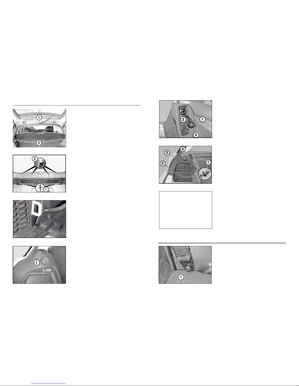
A. PREPTHEVEHICLE
Detach straps (1) and slide the parcel shelf out of
guides (2).
1. REMOVE REAR PARCEL SHELF
Remove the luggage compartment oor panel. Locate
the three expansion rivets (1) at the lower edge of the
sill. Hidden friction clips (2) shown for next step.
2. REMOVE REAR SILL (PART 1)
Remove the center-pin of each expansion rivet with a
at screwdriver or panel removal tool. Pry out the base
of the expansion rivet. Pull the bottom of the rear sill
toward the front of the vehicle to clear the luggage “D”
rings, then pull the whole panel up, popping free the
friction clips (2) shown above.
3. REMOVE REAR SILL (PART 2)
Remove the luggage compartment light (1) by prying
the rear edge down and forward. Unplug the light.
CAUTION: the light may be hot!
4. REMOVE LEFT WHEEL ARCH TRIM (PART 1)
B. RUNTHEPOWER&GROUNDWIRES
Lift the seat catch (1) up halfway. Using a 90 degree
pick or an appropriate panel tool, pry the retaining clips
(2) inward and forward to release them. Remove the
trim piece (3).
5. REMOVE LEFT WHEEL ARCH TRIM (PART 2)
Remove the ve expansion rivets (1). Feed out the
Wheel Arch Trim panel (2). Disconnect the 12V plug
(4).
NOTE: When re-installing the panel, make sure to feed
the seal (3) over the top of the edge of the trim panel
(2).
6. REMOVE LEFT WHEEL ARCH TRIM (PART 3)
Repeat Steps 5 & 6 for the right side.
7. REMOVE THE RIGHT WHEEL ARCH TRIM
Using a Torx T-50 bit, remove the seat belt screw (1)
where it passes through the rear of the door sill trim.
NOTE: Left (Driver’s) side shown, but the procedure is
the same for left & right sides.
8. REMOVE RIGHT DOOR SILL TRIM (PART 1)
3|IntegralAudio|InstallationInstructions Continuedonnextpage...
SeeSteps5&6
4|IntegralAudio|InstallationInstructions Continuedonnextpage...
Remove metal seat belt bushing (1) . Pull Rear Side
Trim Panel (4) in, releasing clip (3) and freeing tab of
Door Sill (2) located behind Side Panel (4).
NOTE: Left (Driver’s) side shown, but the procedure is
the same for left & right sides.
9. REMOVE RIGHT DOOR SILL TRIM (PART 2)
[Seat shown removed for clarity] Pull Door Sill Panel (2)
directly in, releasing clips (3). This requires rm pres-
sure. Remove small trim piece (1) by pulling toward the
rear of the vehicle, releasing a spring clip.
NOTE: Left (Driver’s) side shown, but the procedure is
the same for left & right sides.
10.REMOVE RIGHT DOOR SILL TRIM (PART 2)
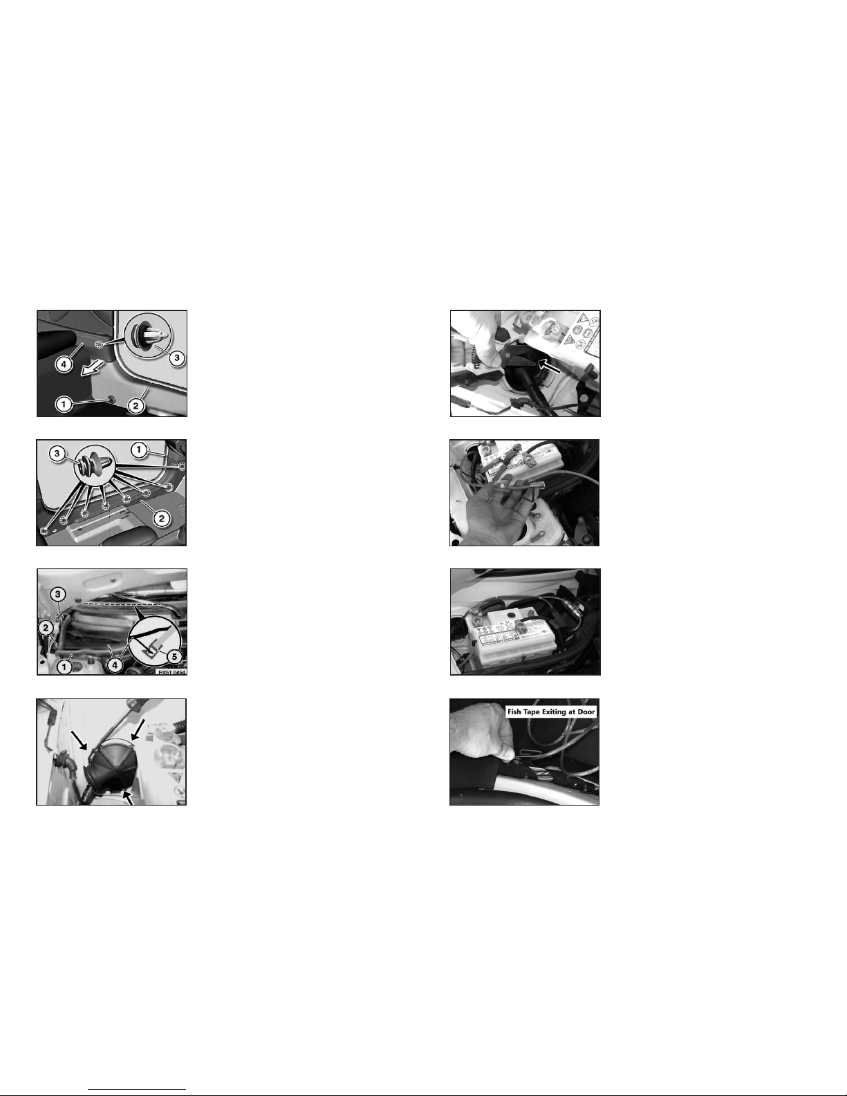
Open the Bonnet (hood). Remove the black plastic
Cowl (4) covering the battery by releasing nuts (2) and
(3) with an 10mm socket. Feed the Cowl out.
NOTE: When replacing the cowl, be sure the seal (1)
is seated properly and that the panel is properly seated
against the windshield (5).
11. REMOVE RIGHT COWL PANEL
Using a at screwdriver, release the indicated retaining
tabs then remove the plastic thru-wall cover to expose
the thru-wall opening.
12. REMOVE THRU-WALL COVER
Cut the end off the spare wiring nipple.
NOTE: Before re-installing the Thru-wall cover, seal the
nipple and power wire with the included electrical tape.
13. CUT SPARE NIPPLE
Cut approx 18” of wire to run from the fuse holder to the
battery. Strip the jacket from the ends of the 8AWG Red
Power Wire. Remove one end cap of the fuse holder
and insert the wire, then secure the gold terminal end
onto the wire with a 4mm Allen wrench. Repeat above
for the other side of the fuse holder using the 18” length
of wire.
14. INSTALL FUSE HOLDER
Mount the fuse holder as shown using 2 of the #6 x ½”
Hex Washer Head screws. Crimp the red ¼” Gold Ring
Terminal to the remaining end of the 18” length of Power
Wire from the previous step. Remove the auxiliary nut
on the battery post with a 19mm socket and attach the
Power Wire.
15. MOUNT FUSE HOLDER
Feed the 8AWG Red Power Wire through the spare wir-
ing nipple and along the Door Sill. Insert your sh tape
from the passenger’s side of the luggage compartment
behind the Rear Right Side Panel and up to the Door
Sill, then use it to pull the Power Wire to the luggage
compartment area.
NOTE: Leave enough slack in the wire to be able to
reinstall the Thru-wall cover.
16. FISH POWER WIRE FROM AMP TO BATTERY
5|IntegralAudio|InstallationInstructions Continuedonnextpage...
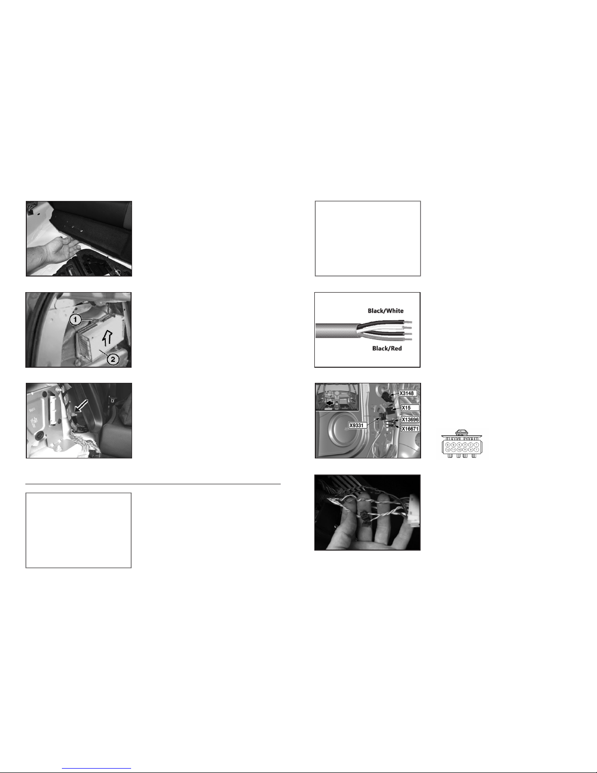
Release the 2 expansion rivets at each side of the
carpet trim covering the raised cross-member at the
front of the luggage compartment. Run the 8AWG
Black Ground Wire from the passenger-side of the lug-
gage compartment to the driver’s side, routing the wire
underneath the carpet.
17. GROUND WIRE (PART 1)
On HiFi-equipped vehicles, it is helpful to temporarily
remove the HiFi amplier to ease access to the wiring.
Release the 10mm nut (1) at the top of the amplier
(2). Remove the amplier by sliding it up and out.
Disconnect the plug by releasing and sliding forward the
locking lever.
18. REMOVE THE AMPLIFIER [HIFI ONLY]
Locate the Common Ground point on the left side of the
vehicle. Remove the nut with a 10mm socket. Strip the
end of the Ground wire, crimp the black ¼” Gold Ring
Terminal to the end, and attach to the Common Ground
point.
19. GROUND WIRE (PART 2)
Repeat Steps 8-10 for the left side of the vehicle.
20. REMOVE DRIVER’S SIDE DOOR SILL
C. SIGNALWIRING(BASESTEREOONLY)
Beginning in the left (driver’s) side footwell, run the
4-Conductor Shielded Signal Wire along the door sill,
behind the Left Rear Side Panel (using the shtape),
under the carpet trim covering the cross member (see
Step 17), ending at the right side of the luggage com-
partment. (see previous images)
21. RUN SIGNAL WIRE
At each end of the Signal Wire, remove 4-6 inches of
the outer jacket and shielding, exposing the 2 twisted
pairs of signal wire. Strip both ends of the 4 signal
wires. At the footwell end, carefully crimp a ¼” Insu-
lated Male Disconnect (these are blue, with a at blade
shaped connector inside) on each wire, 4 total. You
may solder the connections if you aren’t condent in
your crimping tool or ability.
22. PREP SIGNAL WIRE
Locate the X9331 connector in the left footwell. The
X9331 is behind and attached to the larger X15.
Remove both by twisting counter-clockwise ¼ turn and
pulling out. Separate the X9331 from the X15.
23. ACCESS X9331 CONNECTOR
Cut the wrapping and unbundle about 8” of the wiring.
Install the 3M T-taps to each of the wires indicated in
the chart below. Use pliers to make it easier to lock the
tap onto the wire. Double-check that you are selecting
the correct wires by verifying the Pin location. Attach
the correct Signal Wire to each T-tap.
24. MAKE SIGNAL CONNECTIONS
SeeSteps8-10
SeeStep17
X9331
Connector
E. AMPLIFIERMOUNTING&CONNECTIONS
6|IntegralAudio|InstallationInstructions Continuedonnextpage...
Locate the two small gauge solid black wires in the
wiring bundle running up the right edge of the rear
hatch opening. Install a 3M T-tap on either of these
(both carry the same signal). Cut the 18AWG White
Turn-on Lead wire to length, strip both ends, crimp a ¼”
Insulated Male Disconnect on one end, and attach to
the T-tap. Proceed to Step 29.
25. REMOTE TURN-ON WIRE
Run the 4-Conductor Shielded Signal Wire and the
18AWG White Remote Turn-on Lead from the right side
to the left side of the luggage compartment, routing the
wires under the carpet trim covering the cross member
(see Step 17). Cut the wires to length, leaving about
18” excess on each end. (see Step 17 Image)
26. RUN SIGNAL WIRE
At each end of the Signal Wire, remove 4-6 inches of
the outer jacket and shielding, exposing the 2 twisted
pairs of signal wire. Strip both ends of the 4 signal
wires and the remote wire. At the end near the factory
amplier, carefully crimp a ¼” Insulated Male Quick
Disconnect on each wire, 5 total. Solder the connec-
tions if desired.
27. PREP SIGNAL WIRE
D. SIGNALWIRING(HIFIONLY)
Cut the wrapping and unbundle about 8” of the wiring.
Install the 3M T-taps on each of the wires indicated in
the chart below. Use pliers to make it easier to lock the
tap onto the wire. Double-check that you are selecting
the correct wires by verifying the Pin location. Attach
the correct Signal Wire to each T-tap.
NOTE: After making the signal connections, replace the
HiFi amplier removed in Step 18.
28. SIGNAL CONNECTIONS
The amplier mounts against the side of the right rear
wheel well. Cut the Self-Adhesive Foam Padding to
length, remove the backing, and afx to the top of
the horizontal section of sheet metal (the side of the
amplifer will rest on top of this padding). Cut the Velcro
into 3 equal length pieces and afx to the vertical sec-
tion of sheet metal. Attach the other half of the Velcro to
the back of the amplier. Make sure both sides align.
29. MOUNT AMPLIFIER
Cut the 2 feet from the length of 16AWG Speaker
Cable. Split and strip the ends of the remaining 6 feet
of Speaker Wire. Connect one end to the amplier
(bridged). Attach the Banana Plugs to the other end.
(no image)
30. SPEAKER WIRE & BANANA PLUGS
Footwell Connector (X9331) - R56 Base Stereo
Signal : Wire Color: Pin: Connect To Signal Wire:
FrontLeft++ Blackw/RedStripe 5 Red
FrontLeft-- Blackw/VioletStripe 6 Black(fromBlk/RedPair)
FrontRight++ Yelloww/BrownStripe 3 White
FrontRight-- Yelloww/BlackStripe 4 Black(fromBlk/WhtPair)
HiFi Amplier Connector (X10266) - R56 HiFi
Signal : Wire Color: Pin: Connect To Signal Wire:
RearLeft++ Bluew/BrownStripe 37 Red
RearLeft-- Bluew/BlackStripe 29 Black(fromBlk/RedPair)
RearRight++ Brownw/OrangeStripe 8 White
RearRight-- Yelloww/RedStripe 16 Black(fromBlk/WhtPair)
RemoteTurn-on SolidBlack 10 ToAmpRemoteTurn-on
SeeStep17
7|IntegralAudio|InstallationInstructions Continuedonnextpage...
Connect the Power, Ground, and Remote Turn-on Lead
wires. Using the Heat-Shrink Butt connectors, connect
the Signal Wire to the ARC Audio Amplier Pigtail Con-
nector as noted at left. After crimping, gently heat the
butt connectors with a lighter or torch to shrink and seal.
Do not burn the wire!
If not already connected, connect the Remote Turn-on
Wire to the amplier.
31. AMPLIFIER CONNECTIONS
Temporarily replace the Wheel Arch Trim Panels.
Place the subwoofer enclosure in the boot and center
it. Place one Mounting Bracket on either side with the
single large hole centered over the indicated raised area
of the boot oor. Mark the center of all ve holes of the
bracket.
32. MARK FOR BRACKET PLACEMENT
Remove the enclosure. Using the #10 x ¾” Pan Head
Screws, attach the mounting brackets in the spots
marked in Step 32. Replace the enclosure and conrm
hole locations are correctly market. Remove the
enclosure.
33. ATTACH THE MOUNTING BRACKETS
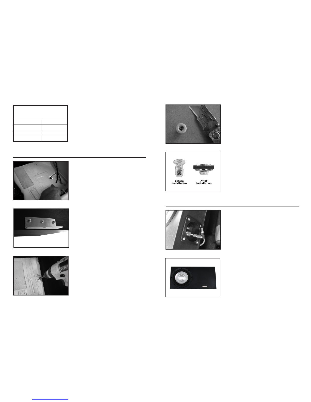
Using a 7/16” bit, drill holes in the 2 positions marked
on the boot oor. Do not let the drill bit penetrate more
than ¼” through the sheet metal. You may nd it helpful
to use a cut-to-length wood block with a hole in the
center as a stop for the drill.
34. INSTALL THREADED INSERTS (PART 1)
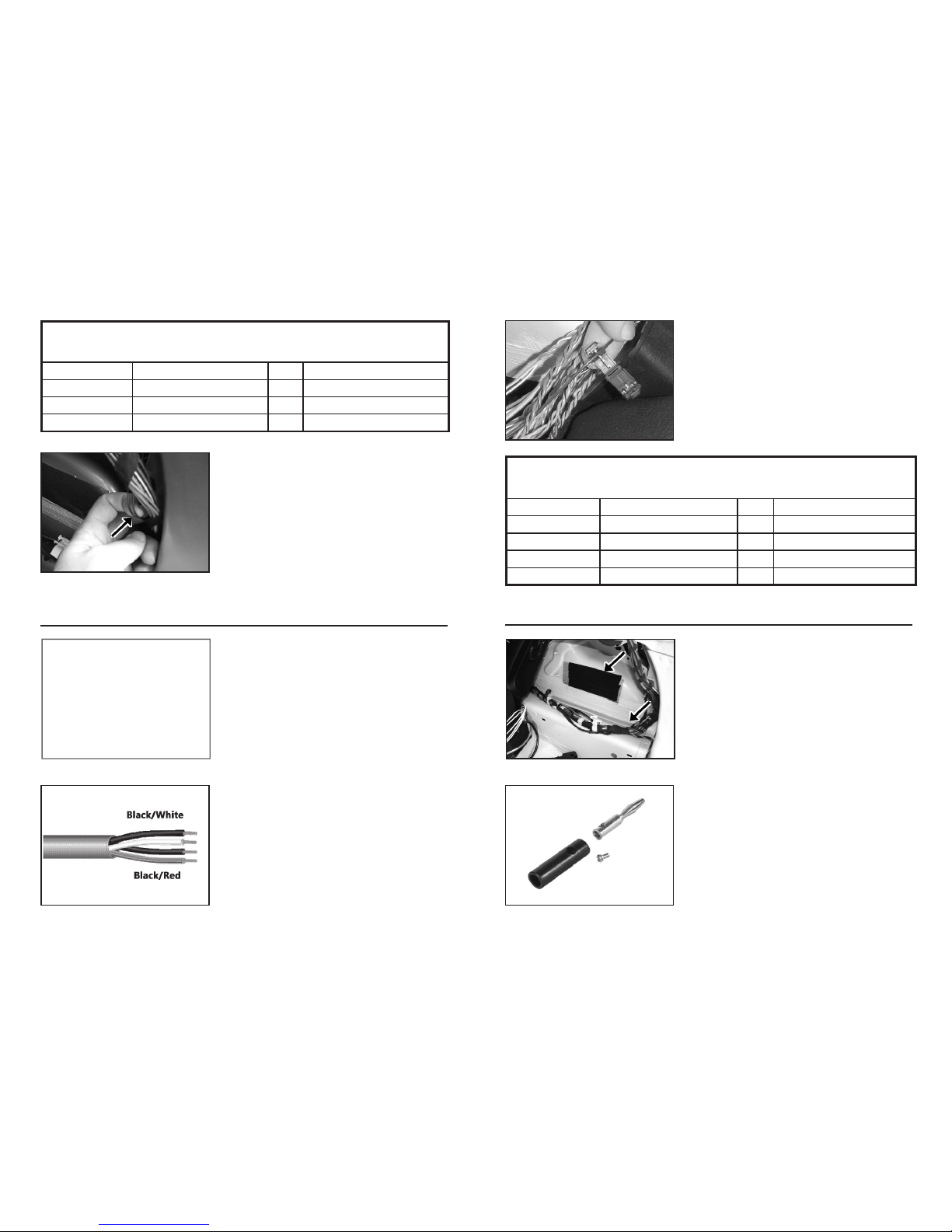
F. INSTALLENCLOSUREMOUNTS
Clean up all metal shavings from the previous step. Us-
ing a utility knife, trim the PVC jacket out of the center
of the -Sealing Threaded Inserts as shown. Insert the
Self-Sealing Threaded Inserts into the holes drilled in
the previous step.
35. INSTALL THREADED INSERTS (PART 2)
Insert the 1” Hex Bolt through the Threaded Insert
Installation Tool and thread the bolt into the Threaded
Insert. Keep the insert ush against the boot oor and
tighten the bolt until the insert is secure but do not over-
tighten. Remove the bolt and repeat for the other side.
36. INSTALL THREADED INSERTS (PART 3)
Split and strip the ends of the remaining 2 feet of
16AWG Speaker Cable. Crimp (and solder if desired)
the 4 female ¼” Quick Disconnects to the wire and
connect to the Terminal Cup. Mount the Terminal Cup
using the #6 x ¾” Black Pan Head Screws.
37. WIRING & TERMINAL CUP
Connect the speaker wiring, observing correct polarity.
Mount the speaker with the #10 x 1” Black Pan Head
Screws. The speaker is a snug t! Tighten the screws
in a “star” pattern, go slowly and take care not to strip
them. Make sure the speaker is mounted ush - the
gasket on the back of the speaker ange should seal.
38. MOUNT THE SPEAKER
G. INSTALLTHEENCLOSURE
Signal Wire to ARC MINI Connections
Signal Wire: Connect to Pigtail:
Red White
Black (from Black/Red pair) White w/Black
White Gray
Black (from Black/Wht pair) Gray w/Black

8|IntegralAudio|InstallationInstructions Continuedonnextpage...
Replace the enclosure in the boot. Connect Banana
Plugs to Terminal Cup. Secure the enclosure with the
Knurled Knobs.
WARNING: Do not allow the Banana Plug connectors
to short (touch each other) when unplugged and the
ignition is on.
39. INSTALL ENCLOSURE
Each of the 3 front supports are assembled with one
Rubber Stand-off, one Cup Washer, and one #10 x 1.5”
Pan Head Screw. The rear supports are twice as high
and are assembled with two Stand-offs (stacked), one
Cup Washer, and one 2.5” Pan Head Screw.
40. MOUNT THE FLOOR SUPPORTS (PART 1)
Place the Floor Supports as shown. Mark and drill a
1/8” Pilot hole. Attach the Supports with the screws.
NOTE: The Rubber Stand-offs may have warped
slightly in transit. To get the rears to stack perfectly,
wrap a few turns of electrical tape around them at the
seam. Remove the tape after they are screwed down.
41. MOUNT THE FLOOR SUPPORTS (PART 2)
The False Floor Panel slides through the hatch opening
and rests on the oor supports. To remove, simply
push down on the edge near the rear seat backs, lift,
and remove - Clean, Simple, Easy!
42. HOW TO REMOVE FALSE FLOOR
H. TESTING&RECOMMENDEDSETTINGS
Reconnect the Battery Negative Terminal and Install
one of the 30 amp AGU fuses in the fuse block. A spare
fuse is included.
43. RECONNECT THE BATTERY & INSTALL FUSE
Once you have conrmed that everything is operating
correctly, reinstall all panels and trim removed during
the installation. Use the provided electrical tape to wrap
and secure all wiring bundles and harnesses, especially
the signal connections at the 3M T-taps.
44. TEST OPERATION
For HiFi-equipped vehicles, recommended amplier set-
tings are listed. Your preferences may vary. Contact us
if you are having difculty or something doesn’t sound
right.
45. AMPLIFIER SETTINGS (HIFI ONLY)
For Base Stereo-equipped vehicles, recommended am-
plier settings are listed. Your preferences may vary.
Contact us if you are having difculty or something
doesn’t sound right.
46. AMPLIFIER SETTINGS (BASE STEREO ONLY)
• Gain: 40% (see ARC manual)
• Output: LOW (low-pass crossover)
• Crossover: 90 Hz
• Bass Boost: 0
• Input: Speaker Level In (button IN)
• Factory Radio Bass Level: -1
• Factory Radio Fade: Front +3
ARC KS125.2 Settings - HIFI
• Gain: 60% (see ARC manual)
• Output: LOW (low-pass crossover)
• Crossover: 80 Hz
• Bass Boost: 0
• Input: Speaker Level In (button IN)
• Factory Radio Bass Level: -1
• Factory Radio Fade: Front +5
ARC KS125.2 Settings - Base
TEST!

• BASS LEVEL CONTROL: HiFi-equipped vehicles can adjust the bass level on-the-y by fading
to the front (decrease bass level) or to the rear (increase bass level). Base Stereo-equipped
vehicles can adjust the bass on-the-y if they perform the front-to-rear channel swap (contact us
for more info). Otherwise, Base Stereo-equipped vehicles adjust the bass level with the Amplier
Gain.
• SIGNAL SOURCE QUALITY: No matter how good the stereo system, a poor quality signal will
always sound poor. If you are using MP3s or home-burned CDs it is critical that you understand
the limitations and impacts of whatever digital compression method you are using. MP3s at less
than 256kbps WILL have noticable loss of quality. Non-commercially obtained music (especially
downloaded via P2P le-sharing) recordings are often re-mixed by third parties and will have
been compressed in an unknown and uncontrolled manner. If you want good quality sound, use
ONLY commercial CDs or MP3s that you have ripped yourself at 256kbps or 320kbps.
• FACTORY RADIO SETTINGS: Remember that settings (Bass, Treble, Fade, Balance, AUX
input level, etc.) are stored on the Key FOB & are specic to the Source (Radio, CD, AUX). You
will need to edit and save the settings for each source and each FOB to have consistent sound.
Allspecicationsaresubjecttochangewithoutnotice.IntegralAudio®andtheIntegralAudiologo,areregisteredtrademarksof
IntegralAudio.Formoredetailedinformationpleasevisitusonlineatwww.integralaudio.com.
www.integralaudio.com
9|IntegralAudio|InstallationInstructions
TROUBLESHOOTING
TIPS & TUNING
Having Trouble? The best thing to do is contact us at [email protected] or via the
phone number listed on the receipt that was emailed to you. We’ll get you xed up!
Tabla de contenidos
Otros manuales de Subwoofer de Integral Audio

Integral Audio
Integral Audio SoundStage + Subwoofer System Manual de usuario

Integral Audio
Integral Audio PHANTOM Manual de usuario

Integral Audio
Integral Audio 1101S Manual de usuario

Integral Audio
Integral Audio PHANTOM Manual de usuario

Integral Audio
Integral Audio MCSS630SW-RAM Manual de usuario

Integral Audio
Integral Audio 81S Manual de usuario

Integral Audio
Integral Audio 1101S Manual de usuario

Integral Audio
Integral Audio 1101S Manual de usuario


