Intec CS4000 Instrucciones de montaje

Version 2 |NOV 2015
Intec ColorSplash CS4000 and CS5000
Enhanced Print Production Envelope Feeder
Installation and Set Up Guide

CONTENTS
1. GETTING STARTED
1.1. ColorSplash EPP Envelope Feeder Components 3
1.2. Control Panel Components and Features 4
2. INSTALLATION GUIDE 5
2.1. Preparing the INTEC CS4000 / CS5000 Printer for use with your
Intec EPP Envelope Feeder 5
2.1.1. Removing the MPT Tray/Door 5
2.1.2. Removing the Outer Separation Pad 6
2.1.3. Installing Non-Reflective Aid for Envelope Feeders Optical Sensors 6
2.2. Assembly of the Intec ColorSplash Envelope Feeder 7
2.2.1. Assembly of Top Plate 8
2.2.2. Assembly of the Feeder Bridge 8
2.2.3. Fitting the Paper Hold Down Strap 9
2.2.4. Positioning the Envelope Buckle Separator 10
3. OPERATING GUIDE 11
3. Setting up the Feeder for envelopes 11
3.1. Setting the Hopper Paper Guides 11
3.2. Setting the Envelope (Buckle) Separator(s) 13
3.3. Setting up the Back Wedge 16
3.3.1. Purpose of the Back Wedge 16
3.3.2. Setting the Back Wedge for small / medium envelopes 16
3.3.3. Setting the Back Wedge for large envelopes 18
3.4. Setting the Acceleration Table Paper Guides 19
4. CHECKING YOUR FEEDER SETUP 21
5. DAILY OPERATION (Running envelopes with your printer) 22
5.1. Mounting/Connecting your Envelope Feeder 22
5.2. Envelope Feeder’s latch mechanism 23
5.3. Setting the Feeder’s speed control 24
5.4. Resume feeding switch /paper out sensor control 24
5.5. Paper jam or feeder out condition 25
5.6. Setting the Intec ColorSplash Envelope Feeder’s speed control 26
5.7. Removing the Feeder from the printer 26
6. TROUBLESHOOTING 27
6.1. Note on new ColorSplash printers 27
6.2. Common issues 27
2
1. GETTING STARTED
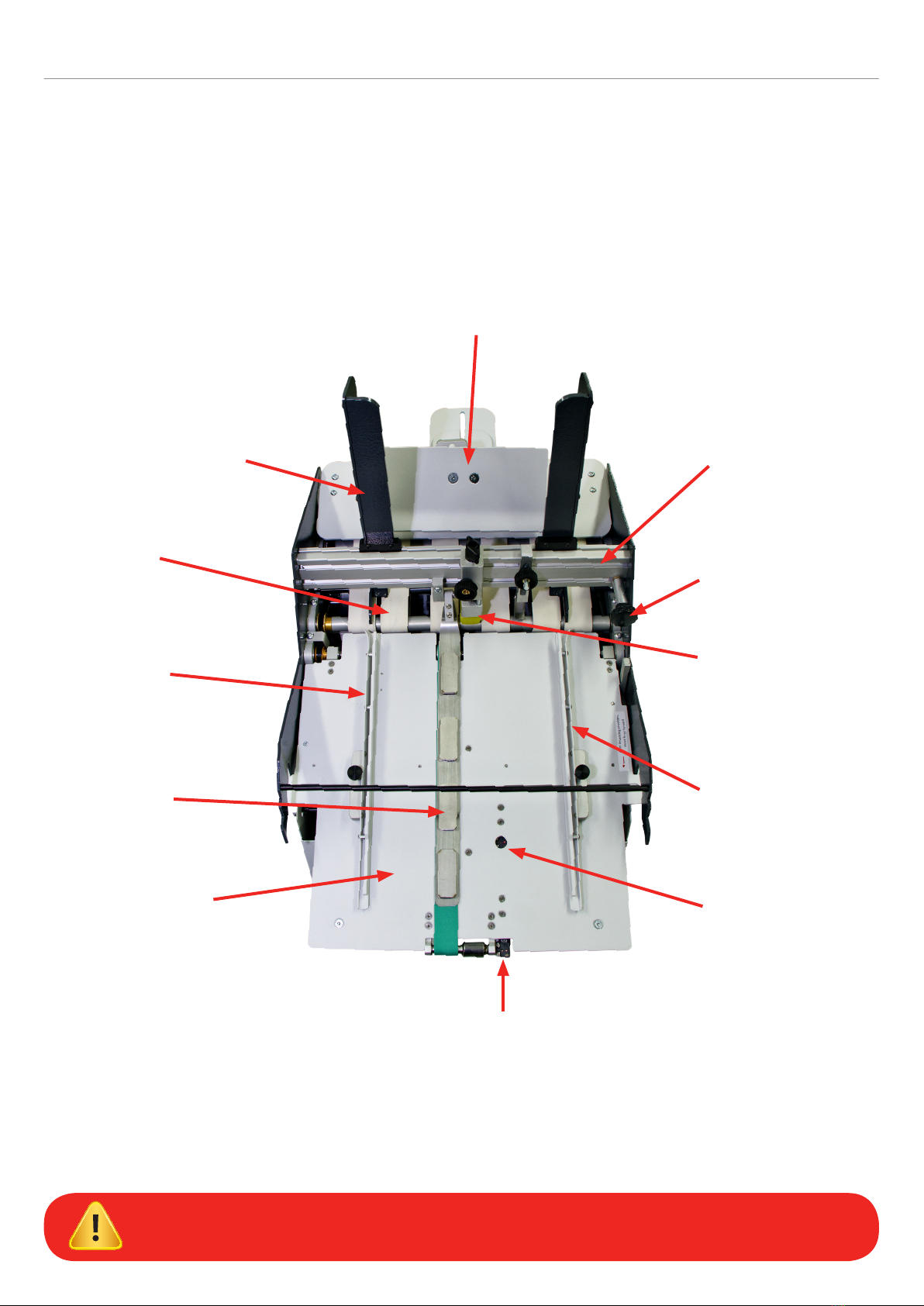
1.1. ColorSplash EPP Envelope Feeder Components
Back Wedge assembly
Paper guide assembly Bridge
Paper guide hopper
adjustment knob
Buckle separator assembly
Acceleration table
paper guide
Optical sensor
(RESTART envelopes)
Optical sensor (STOP envelopes)
Acceleration table
Envelope hold
down strap
Acceleration table
paper guide
Feed belts
IMPORTANT: Please familiarize yourself with the components shown above. These
components are referred to in the setup instructions contained in this manual.
3

1.2. Control Panel Components and Features
Timeout reset / Jog button*
24 VDC power input jack Fuse holder (5 amp fuse)Ready/Feed switch Speed adjust knob
Mains power switch
The ColorSplash’s EPP Envelope Feeder
features a timeout function. During
operation, if the optical sensor mounted at
the exit end of the acceleration table (the
STOP Envelope Sensor) does not detect
an envelope for 4 seconds, the feed motor
will be paused. This is to ensure that the
motor does not ‘run on’ in the event the
feeder runs out of envelopes, or a jam
occurs in the feeder.
The Reset / Jog button shown above is
used to reset the timer and allow the motor
to restart running after a timeout occurs.
If you press and hold this button in,
the motor will run continuously until an
envelope covers the optical stop sensor.
The variable speed control can be
adjusted to accommodate different size
envelopes. As a general rule, most small
envelopes will require approximately 50%
maximum speed or more. For envelopes
150mm (6" long) in the running direction or
longer, higher speeds will be required for
consistent operation.
The feeder utilizes a low voltage 24 VDC\5
amp external power supply. An on board
5 amp fuse is included for electrical
component protection. This fuse can be
accessed by unscrewing the fuse cap in
the lower right corner of the control panel.
*TIMEOUT FEATURE
4

2. INSTALLATION GUIDE
The Intec ColorSplash’s EPP Envelope Feeder is designed to operate with the new Intec ColorSplash digital production
printers. This guide will show the proper way to prepare the printer for the envelope feeder and installation and operation
of the feeder.
2.1. Preparing the INTEC CS4000 / CS5000 Printer for use your Intec EPP
Envelope Feeder
2.1.1. Removing the MPT Tray/Door
Step 4. Remove the left side of the door in the same
fashion and remove the door from the printer.
Step 3. Press inward on the pivot point of the
door on the right side to remove it
from the printer housing.
Step 2. Press inward on the right side hinge
of the door to release it from the slot.
Step 1. To prepare the ColorSplash CS4000/
CS5000 printer for the feeder, you must
first remove the door from the manual
feed tray. First, open the manual feed
tray door on the right side of the printer.
5
1
3
2
4
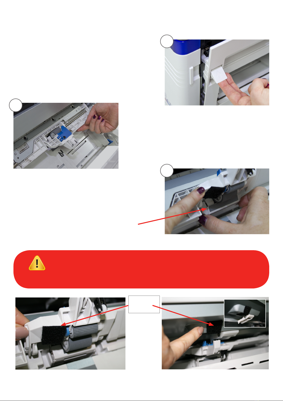
2.1.2. Removing the Outer Separation Pad
Step 6. With the right side door fully open,
lift the feed roller assembly to gain
access to the feed roller and sheet
separator area.
Step 7. Pinch the two upper corners of the
sheet separator assembly (rubber
pad) and remove the assembly from
the printer.
Remove the separator assembly
NOTE: The envelope feeder is equipped with paper sensors positioned just to the left of
the printer’s manual feed tray feed roller and in the centre of the floating delivery table. It is
possible for the sensors to detect the white plastic housing just to the left of the feed roller,
and reflective silver housing above the middle sensor, which can cause erratic feeding.
It is very important to place the black tape or Velcro™ (included with feeder) in these 2 positions.
Note: This tape will not affect the printer and can be left in place, even when not using envelope feeder
Place black
tape
in these areas
6
Step 5. Open the right side cover on the printer by
pulling on the latch shown here:
5
6
7

2.2. Assembly of the Intec ColorSplash Envelope Feeder
Step 1. After removing the feeder from the shipping container, carefully place the feeder
and cabinet in the upright position.
Step 2. Open the door on the rear of the cabinet and remove the accessories box.
Step 3. Carefully remove the contents of the accessories box and set them on a table.
Ensure that all of the components listed below are accounted for before discarding the packaging.
Additional items included in the accessories box include:
• Extra sheet separator
• Envelope buckle device
• Black Velcro™ patches for printer
• 24 VDC power supply
• Narrow back wedge assembly
Hold down strap and shoulder screw
Top plate and back wedge assembly
Bridge
1/8" Allen wrench
7

5
7
8
9
2.2.1. Assembly of Top Plate
Step 4. Using the included 1/8" Allen wrench, remove
the four button head screws from the top of
the back plate of the feeder.
Step 5. Attach the top plate to the feeder
using the four button head screws
removed in Step 4.
Step 6. Tighten the screws holding the top
plate securely.
Step 7. Using the 1/8" Allen wrench, remove the two flat
head screws from each end of the bridge.
Step 8. Carefully position the bridge between the
side plates of the feeder and line up the
attaching holes.
2.2.2. Assembly of the Feeder Bridge
Step 9. Attach the bridge to the feeder using
the four flat head screws removed
from the bridge in Step 7.
Step 10. Tighten all four bridge screws.
Do not tighten any of the screws until
all four are in place.
Be careful on steps 4 & 5 not to drop
the screws into the feeder.
8
4

2.2.3. Fitting the Paper Hold Down Strap
Step 11. Remove the shoulder screw from the paper hold down strap pivot block.
Step 12. Place the end of the hold down strap (opposite pivot
block end) underneath the acceleration table cross bar
and on top of the transport belt.
Step 13. Position the hold down strap pivot block next to the
mounting block (on the right side) on the bridge and
insert the shoulder screw into the pivot block.
Step 14. Attach the pivot block to the mounting block on the
bridge using the 1/8" Allen wrench to tighten securely.
The hold down strap assembly should
pivot at the shoulder screw and should lie
flat on the transport belt.
The steel weights on the strap apply downward
pressure on the envelopes to ensure consistent
movement of the envelopes by the transport belt.
Strap weights
Pivot block for paper
hold down strap
Shoulder screw
9
12
13
14

15
16
17
2.2.4. Positioning the Envelope Buckle Separator
Step 15. Loosen the locking knob holding the envelope buckle
separator in position on the bridge.
Step 16. Slide the buckle separator to the
center of the feeder and position the
yellow tip at the bottom between
the two center feed belts as shown
in the photo.
Step 17. Lock the separator
in position with the
locking knob.
10
Otros manuales para CS4000
2
Este manual sirve para los siguientes modelos
1
Tabla de contenidos
Otros manuales de Impresora de Intec


