Inta Hiper II V1 Manual de usuario

In this document Inta have endeavoured to make all the information and procedures accurate. Inta cannot accept responsibility should it be found that in any respect the information is inaccurate or incomplete as a result of future developments. Installation and Operating Manual Hiper II V1 Heating onlysingle plate HIU e&oe 07/22

Annual servicing is required to ensure that the conditions of the warranty are met. Required Hiper HIU documents. 1. Installation and Operating Manual (this document) 2. Operation and Maintenance Manual (included with the HIU) 3. Commissioning report (included with the HIU) 4. Programming Manual (available on request, contact Inta before commissioning) These instructions describe the installation and operation and fault finding diagnostics of the Hiper II V1 Heat Interface Unit (HIU). For operation of the entire plant, the technical documentation of all the components used such as, boiler, tank, pumps, pipework and valves must be complied with. Inta does not accept any responsibility for the design and performance of the heat network or components outside of the HIU, demarcation being the HIU isolation valves at the connection to the HIU. Installation should only be carried out by a qualified and competent plumbing installer and a qualified and competent electrical installer in accordance with the current Building, Water and Electrical Regulations, Legislation and Standards. Do not start installation until you have thoroughly read and understood all the Installation and Operating Instructions as listed above, and have complied with all safety provisions required. DANGER – immediate risk of physical injury or even death. DANGER – immediate risk of serious damage. IMPORTANT – information critical to the installation or installer. IMPORTANT – information critical to the user. NOTE – useful information regarding the operation or installation of the HIU. SECTION 1 - Important information and introduction Symbols used in these documents Do not tamper or make any alteration to the earthing connections provided as indicated on the casing with the provision of an earthing label! One earthing point is on the outside of the lower casing, underneath the HIU. The other is inside the HIU on the casing backplate. Each earthing connection is provided with a metric Earthing label Earthing Instructions, take note! Page 2 e&oe 07/22

SECTION 2 - Dimensions and components A 585 mm Height B 465 mm Width C 265 mm Depth D 100 mm Pipe Distance E 140 mm Pipe Distance Dimensions Clearances F Sides 30mm G Below 300mm H Above 200mm I In front 50mm D E * clearance of at least 300mm to allow the cover to be removed! Due care must be given by the installer that the cover, heat meter viewing door and components are all accessible! Isolation valves ordered separately as accessory pack HIAC03BVPACK.Page 3 A C B G F H I Inta Description Inta Code HIPER II V1 HEATING ONLY Single Plate HIU with Ista Heat Meter HIPER2SPHOIS HIPER II V1 HEATING ONLY Single Plate HIU with Zenner Heat Meter HIPER2SPHOZE HIPER II V1 HEATING ONLY Single Plate HIU (NO HEAT METER) HIPER2SPHONM e&oe 07/22

Schematic Page 4 SECTION 3 - Schematic e&oe 07/226 7 DH Return 1 11 4 10 9 9 6 8 12 Heating Return 9 DH Flow 2 4 9 Heating Flow 16 15 12345678Drain and vent valvesStrainer with drain valvePocket for heat meter sensorIsolation valvesPressure independent control valvesPlate heat exchanger (PHE)Expansion vesselLow pressure switch910111213141516Temperature sensorsTemporary bypass accessoryHeat meter or temporary spacer pipeSafety relief valveCirculation pumpAutomatic air ventPressure gaugeFilling group

SECTION 4 - Components Page 5 11 14 1. Drain and air venting valves 2. Strainer with drain cap. 3. Pocket for installing heat meter temperature sensor. 4. Isolation Valves (ordered separately). 5. Pressure independent control valve (PICV) and fast acting stepper actuator. 6. Circulating pump for secondary heating. 7. Automatic air vent. 8. Safety pressure relief valve. 9. Low pressure switch. 10. Plate Heat Exchanger. 11. Expansion vessel 8 Ltr. 12. Pressure gauge 13. Temporary bypass or test ports. 14. NTC temperature sensors 15. Heat Meter position or temporary spacer pipe 110mm. 16. Electronic PID controller e&oe 07/22

SECTION 5 - Accessories ACCESSORIES for HIPER 2 TWIN PLATE HIU Part Code Pack of 4 Secondary straight isolation valves. HIAC03BVPACK Pair stand off wall brackets (to allow for pipes to be run behind the HIU). HIAC01SOBPACK Flushing By Pass Kit A for internal installation. (temporary pipe). HI2AKITA Flushing By Pass Kit B for internal installation (Fixed connection to HIU with shut off valve). HI2AKITB Flushing By Pass Kit C (valve and tee fittings) for external installation. HI2AKITC First fix JIG.(use as a template for first fix piping, use with HIACPFFKIT) HI2ACJIG Pack of 4 Secondary straight isolation valves. HIAC03BVPACK Prepayment relay (for billing systems using a 230v signal). HIAC04230KIT Security - anti-tamper fixing screws + driver. HIAC05SSPACK Insulation jacket for HIU isolation valve. ARM022129 Pack of 4 Secondary isolation valves.HIAC03BVPACK Pair stand off wall brackets. HIAC01SOBPACK First Fix Jig Using the Jig allows pipe work to be installed without the HIU. HI2ACJIG.Same Jig is used for all Hiper II HIU so only use the heating connections. Temporary By Pass Kit A HI2AKITA Temporary By Pass Kit C HI2AKITC Temporary By Pass Kit B HI2AKITB X X Page 6 e&oe 07/22

6.1 Before installation read and comply with the following Comply with all safety provisions. Do not tamper with the earthing connections as indicated on the casing. To secure the casing when closing the cover, use the provided M4 screw and washer to ensure earth continuity on the casing.The Installer’s Responsibility - in accordance with Part L of the Building Regulations, all hot and cold water pipes should be labelled and insulated to the current standards. Installation should only be carried out by a qualified and competent plumbing installer and a qualified and competent electrical installer in accordance with the current document Building Regulations, Legislation and Standards. It is the installer’s responsibility to ensure that the place of installation and wall is suitable. An unsuitable location or provision of adequate supplies (Primary Heating and Cold Water mains) will not justify any warranty or fault claim; •The wall must be capable of bearing the weight of the HIU when permanently filled with water.•Locations where access is restricted for maintenance, see page 3. •The HIU is only for WALL MOUNTING in the orientation shown in this manual. •Locations where criminal damage or illegal tampering cannot be reasonably preventable.•Locations where discharge pipe is not able to be safely or legally installed and connected.•Supplies which are not suitably clean, and free from contaminants. •Supplies which contain chemical contaminants. •On site precautions must be made by the installer to protect the unit from builders’ dust and debris. Wall fixing bolts are to be provided by the installer and be suitable to bear the weight of the HIU when permanently full of water. SECTION 6 - Installation 6.2 Consider which installation method is to be used. 1. HIU as delivered to site. 2. HIU and stand off brackets as delivered to site 3. HIU JIG at First Fix Pipe work stage, with the HIU to follow later. 4. HIU JIG and stand off brackets, with the HIU to follow later. 6.3 General installation notes .1. Ensure all pipes are labelled and insulated in accordance with Part L of the building regulations.2.The HIU can only be installed in one orientation, with the heat network connections at the top, and in a vertical position. Before removing the cover turn off the power supply at the mains (fused spur 230v 50Hz). Page 7 e&oe 07/22

SECTION 6 - Installation 6.4 Ensure the chosen installation site is inside the building, weather proofed and provides good access for maintenance, minimum requirements as on page 3. Note where and which pipe connections will be required, and pay attention to where the safety valve discharge pipe will terminate, and ensure this meets all current building regulations and has a continuous fall. 6.5 Making sure the wall the HIU is to be mounted on complies with 5.1, mark up the position for the wall bracket. The position of the HIU is to be on a true vertical plane as in 5.3. Drill and plug the wall, and secure the HIU with suitable wall fixings (not provided with the HIU). Page 8 90o Hang on to the wall bracket hooks and position the HIU against the wall. 6.6 Plumbing Connections A Heat Network Flow B Heat Network Return C 3/4” Heating Flow (radiators or underfloor heating. D 3/4” Heating Return E 1/2” Safety valve discharge F Cold water connection for filling. Installer to provide isolation stopcock. Make connections with HIAC03BVPACK Isolation valves with flat face unions and gasket seals (ordered separately). A B E C D F e&oe 07/22
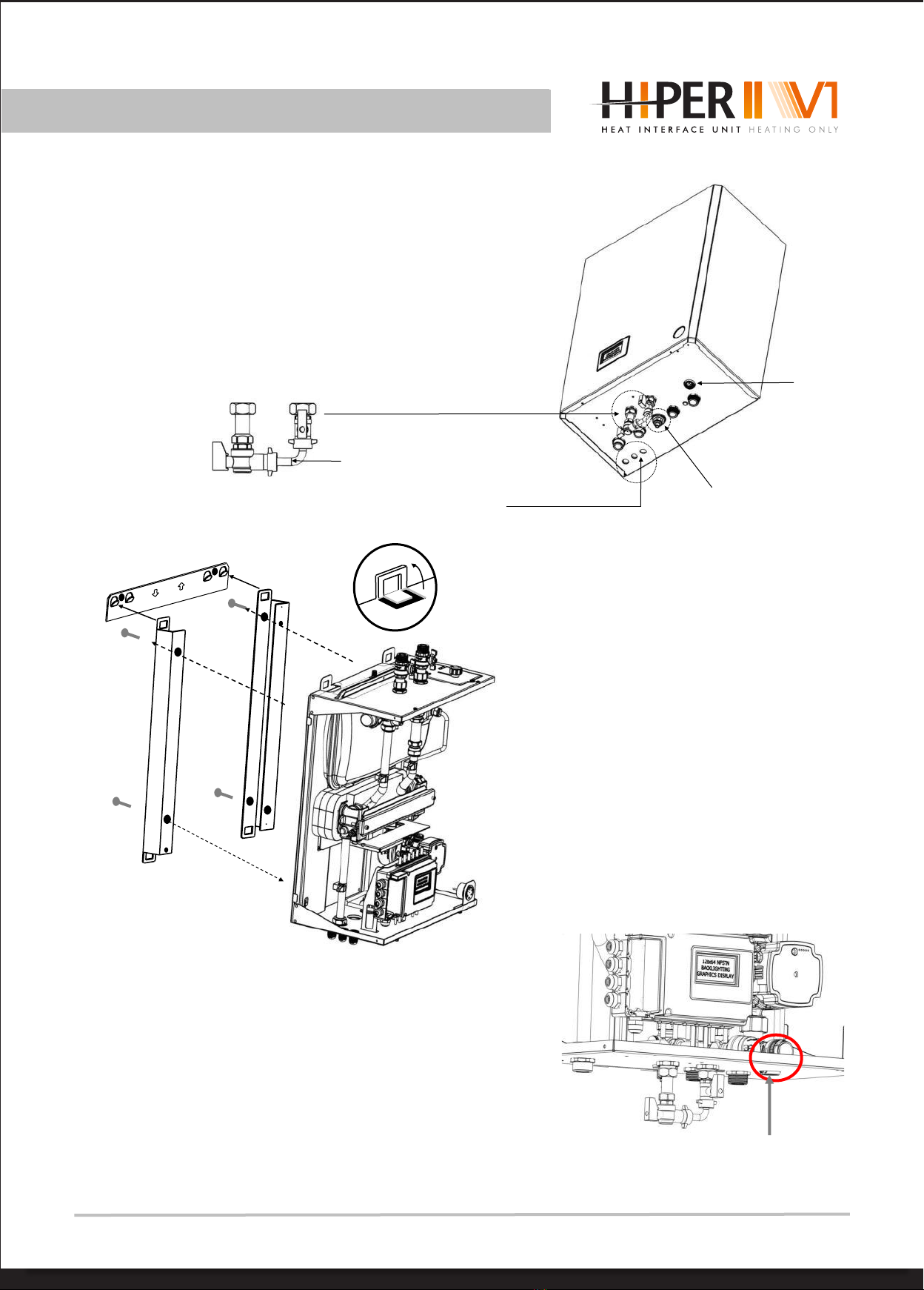
SECTION 6 - Installation Accessory option - stand off brackets (SOB) 6.8 Stand off brackets create a space behind the HIU that can be used to run pipes in. The stand off brackets are 40mm off the wall allowing for 13mm pipe insulation thickness. First attach the brackets using 4 x fixing screws to the back of the HIU in the matching fixing holes provided. Fit the wall bracket as in 5.6 and per 5.1 Then hang the HIU as in diagram 5.6, but this time using the outer wall bracket hooks. 6.9 Safety valve discharge pipe. The safety valve has a 1/2” F threaded connection for 15mm pipe to be connected to (15mm x 1/2” M compression coupling to be provided by the installer). The discharge pipe should have a continuous fall and conform to BS6798. Where the pipe empties into a drain then that area must be frost free, and consideration as to a trap being included as well as a tundish to ensure any discharge is fully visible. Discharge connection Page 9 6.7 For filling the Heating Circuit for the radiators or UFH, the filling valves and connecting pipes are integral to the HIU. This may be removed while pipe work and isolation valves are made good. Refit when commissioning. On completion of filling the Heating Circuit the temporary con-nection pipe between cold Water supply should be removed. Place safely inside the unit for future filling operations. Cold water filter Electrical connections cable glands. Safety valve discharge connection Temporary connection pipe. Remove after filling. Use outer bracket hooks. e&oe 07/22

SECTION 6 - Installation 6.10 Flushing Bypass Kits - instructions for KIT A and B · See section 6, HIU wiring complete. HIU turned off to close the PICV. · All HIUs on this circuit must be flushed using this method at the same time. · Close the isolation valves as shown, and empty of water through the drain valve into a bowl. · remove test port plugs. · Install the kit adaptors making water tight seal on the O rings of the adaptors. · Fix the flushing pipe in position as shown, tighten the union nuts making a water tight seal with the fibre · washers provided. · Open the isolation valves for system flushing. · When the flushing operation is finished, close the isolation valves as shown below, and empty water through the drain valve again. · Now remove and clean the filter mesh by undoing and removing the filter cap. · Replace the now clean filter mesh, and replace the filter cap. Remove and store the flushing pipe, replace the test plugs and make water tight. Do not over tighten the O rings. · Fill the HIU, ready for commissioning. For External Flushing bypass valves use the above as guidance and follow the instructions included with the valve Adaptors and fibre washers Test ports with plugs Drain Filter cap Flush pipe Page 10 Temporary By Pass Kit A HI2AKITA Temporary By Pass Kit C HI2AKITC Temporary By Pass Kit B HI2AKITB Check Connections! •Flow and Return in correct positions? •All union nuts have been tightened, and a visual inspection expects them to be water tight.•All union nuts inside are tightened, and a visual inspection expects them to be water tight. All isolation valves in the closed position All drain valves and air vent valves are closed. Close the Primary Isolation Valves e&oe 07/22
Tabla de contenidos
Otros manuales de Sistema de calefacción de Inta


