inFusion 800 Manual de usuario

Installation, Operation and
Maintenance Manual
Infusion Oxi-Boost Residential
Iron, Manganese & Sulfur
Removal Systems
Iron, Manganese & Sulfur Removal
Infusion Oxi-Boost Iron Filters
169-IOB-1
169-IOB-2
169-IOB-3
169-IOB-4
US Water Systems, Inc.
1209 Country Club Road
Indianapolis, IN 46234
1-800-608-8792
info@uswatersystems.com
www.uswatersystems.com
REVISION 2.2, 12/2/2013

2
Installation, Operation and Maintenance Manual
169-ISF-1, 169-ISF-2, 169-ISF-3 & 169-ISF-4
Table of Contents
Introduction and Benefits ........................................................................3
System Overview....................................................................................4
Infusion Tank Installation ........................................................................5
Media Installation....................................................................................5
Installation Instructions Chemical Pump Pipe and Drain Connections ...7
Infusion Start-Up………..…………………………………………………….12
Timer Features……………………………………………………….……….14
Programming Infusion Valve and Chemical Pump………………………...16
Time of Day Settings……………………………………………………….…18
Initial Regeneration…………………………………………………………...18
Limited Warranty Details………………………………………………..……19
Limited Lifetime Warranty……………………………………………….…...20

3
Introduction
The Infusion system provides iron, sulfur and manganese removal throughout the home. The
Infusion system should be installed at the point of entry to treat your entire home, both hot and
cold water.
The Infusion backwashing tank removes iron, sulfur and manganese using oxidation. When
the system regenerates, hydrogen peroxide is injected as air is pulled into the tank which
creates an “air space” for the water to pass through and super oxidation during regeneration
using hydrogen peroxide. The oxygen in the air space and the peroxide oxidizes the
contaminants and separates them from solution so they can be removed by filtration. The
media in the Infusion tank provides this filtration. This system should regenerate every night
to ensure that an adequate air space is maintained in the Infusion tank.
Infusion Benefits
Iron, Manganese & Sulfur Removal
Virtually maintenance free.
Improves the efficiency of water-using appliances
Simple installation
Safe for landscaping and lawn watering.
Compatible with all on-site and community wastewater treatment systems
Installation, Operation and Maintenance Manual
169-ISF-1, 169-ISF-2, 169-ISF-3 & 169-ISF-4

4
System Overview
Installation, Operation and Maintenance Manual
169-ISF-1, 169-ISF-2, 169-ISF-3 & 169-ISF-4

5
Infusion Tank Installation Instructions
WATER PRESSURE: A minimum of 20 pounds of water pressure is required for regeneration valve to oper-
ate effectively.
ELECTRICAL FACILITIES: An uninterrupted alternating current (A/C) supply is required. Note: Other
voltages are available. Please make sure your voltage supply is compatible with your unit before in-
stallation.
EXISTING PLUMBING: Condition of existing plumbing should be free from lime and iron buildup. Piping
that is built up heavily with lime and/or iron should be replaced.
LOCATION OF INFUSION TANK AND DRAIN: The Infusion tank should be located close to a drain to pre-
vent air breaks and back flow.
BY-PASS VALVES: Always provide for the installation of a by-pass valve if unit is not equipped with one.
CAUTION: Water pressure is not to exceed 80 psi, water temperature is not to exceed 110°F (43°C), and the
unit cannot be subjected to freezing conditions.
Media Installation
1. Use a piece of duct tape to cover the top of the distributor tube. Be sure the distributor tube is cen-
tered in the tank. Install the supplied funnel and pour the gravel in the tank. If you purchased multi-
ple systems, there will be several boxes. Each system and the boxes associated with the system will
be marked with the respective system’s part number. Match the part numbers on the boxes to be
sure you have the correct components and media for each system. Pour the gravel in the tank first
then pour in all the carbon that was shipped.
Installation, Operation and Maintenance Manual
169-ISF-1, 169-ISF-2, 169-ISF-3 & 169-ISF-4

6
2. Lubricate the distributor tube O-ring seal and tank O-ring seal. Install the upper basket on the bot-
tom of the valve. Place the main control valve on tank. Note: Only use silicone lubricant. Turn the valve
clockwise until it is hand tight. Give it a couple taps with the palm of your hand to tighten further. DO
NOT use tools to tighten the valve because damage could occur with the use of pipe wrenches or chan-
nel locks.
Installation, Operation and Maintenance Manual
169-ISF-1, 169-ISF-2, 169-ISF-3 & 169-ISF-4
7
Installation Instructions
Place the Infusion tank where you want to install the unit making sure the unit is level and on a firm base.
During cold weather, the installer should warm the valve to room temperature before operating.
All plumbing should be done in accordance with local plumbing codes. The pipe size for residential drain line should
be a minimum of 1/2" (13 mm). Backwash flow rates in excess of 7 gpm (26 Lpm) or length in excess of 20 (6 m)
require 3/4" (19 mm) drain line. Commercial drain lines should be the same size as the drain line flow control.
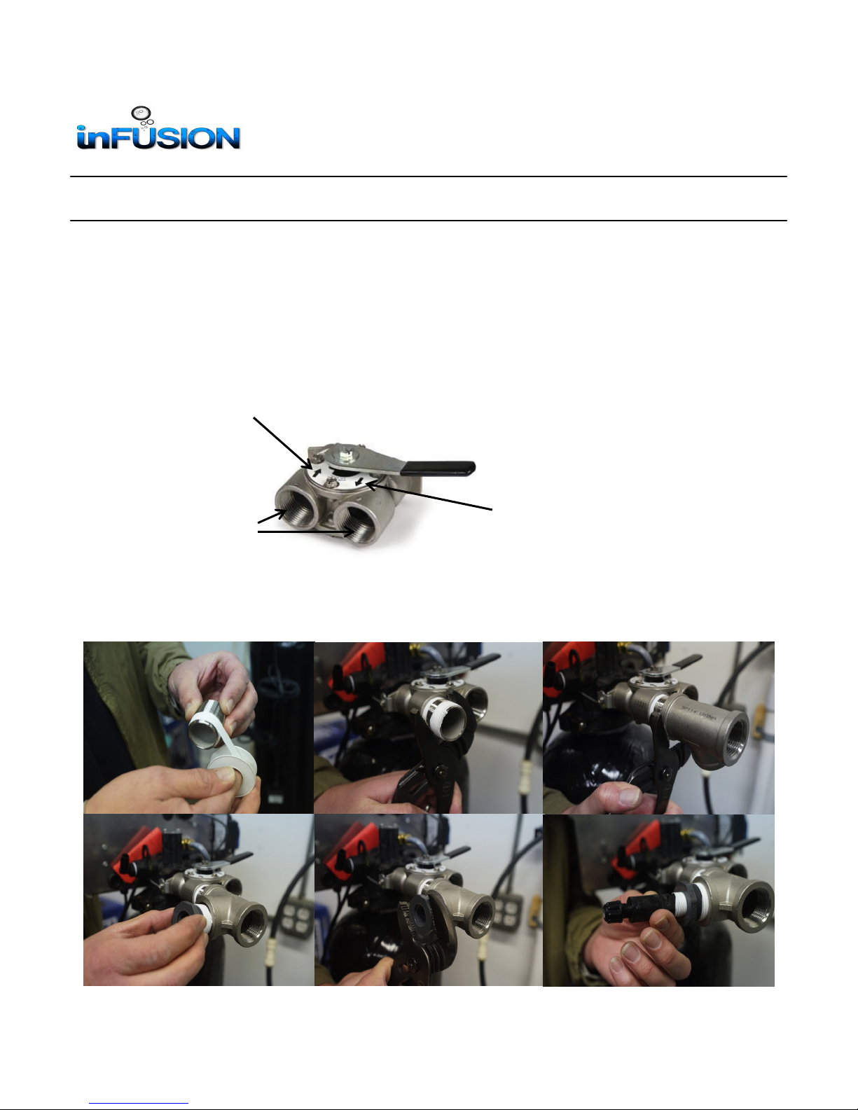
1. The unit is equipped with a 1” NPT female bypass. Attach the piping to the bypass. Be sure to connect the
plumbing properly. There are arrows on the bypass that indicate flow. The arrow pointing toward the unit is
the “inlet” connection and the arrow that points away from the unit is the “outlet” connection. It is a good
practice to install a air catch loop in the outgoing plumbing. See “System Overview” drawing.
2. First add Teflon thread tape to all the injection fittings. The close stainless steel nipple will be installed in the
bypass inlet port. Now install the stainless steel tee on the close nipple that was installed in the bypass inlet
port. Install the 1” x 1/2” PVC reducing bushing in the tee.
In
Out
1”
NPT
Installation, Operation and Maintenance Manual
169-ISF-1, 169-ISF-2, 169-ISF-3 & 169-ISF-4

8
Installation, Operation and Maintenance Manual
169-ISF-1, 169-ISF-2, 169-ISF-3 & 169-ISF-4
3. Now add Teflon thread to the injector and install it in the PVC reducing bushing.
4. Connect the inlet plumbing to stainless steel tee and the outlet plumbing should be connected to the outlet
port on the bypass.

9
Installation, Operation and Maintenance Manual
169-ISF-1, 169-ISF-2, 169-ISF-3 & 169-ISF-4
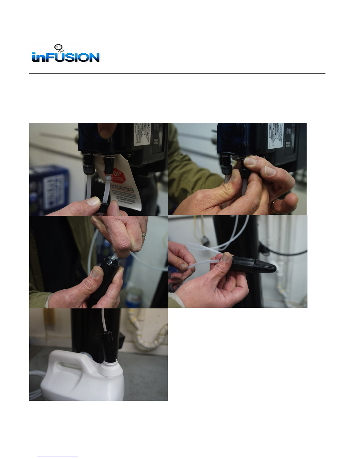
5. Connect a piece of tubing from the injector to chemical pump outlet. There are arrows on the chemical pump to
show direction of flow. The arrow pointing down will be the chemical pump outlet.
10
Installation, Operation and Maintenance Manual
169-ISF-1, 169-ISF-2, 169-ISF-3 & 169-ISF-4
6. Now connect a piece of the tubing to the chemical pump inlet. The inlet will have and arrow point up. Make
sure to leave enough tubing to reach the peroxide container. Cut the tubing to fit and push the weighted strain-
er on the other end of the tubing. Push the weighted strainer down in the peroxide tank.
Este manual sirve para los siguientes modelos
6
Tabla de contenidos


