Infineon TLE493D-A2B6 Manual de usuario

3D Magnetic Sensor 2 Go - TLE493D-A2B6
Low Power 3D Hall Sensor with I²C Interface
TLE493D-A2B6 3D-MS2GO
User Manual
About this document
Scope and purpose
This document provides an introduction to the 3D Magnetic Sensor 2 Go kit and should enable the reader to
eiciently carry out own evaluations with the 3D magnetic sensor TLE493D-A2B6.
Intended audience
This document is aimed at everyone who wants to work with the 3D Magnetic Sensor 2 Go evaluation kit.
User Manual Please read the Important Notice and Warnings at the end of this document 1.0
www.infineon.com 2018-05-16
Downloaded from Arrow.com.

Table of contents
User Manual . . . . . . . . . . . . . . . . . . . . . . . . . . . . . . . . . . . . . . . . . . . . . . . . . . . . . . . . . . . . . . . . . . . . . . . . . . . 1
About this document . . . . . . . . . . . . . . . . . . . . . . . . . . . . . . . . . . . . . . . . . . . . . . . . . . . . . . . . . . . . . . . . . . . 1
Table of contents . . . . . . . . . . . . . . . . . . . . . . . . . . . . . . . . . . . . . . . . . . . . . . . . . . . . . . . . . . . . . . . . . . . . . . . 2
1 Introduction . . . . . . . . . . . . . . . . . . . . . . . . . . . . . . . . . . . . . . . . . . . . . . . . . . . . . . . . . . . . . . . . . . . . . . . . . . . 3
1.1 Hardware overview . . . . . . . . . . . . . . . . . . . . . . . . . . . . . . . . . . . . . . . . . . . . . . . . . . . . . . . . . . . . . . . . . . . . . . 3
1.2 Soware . . . . . . . . . . . . . . . . . . . . . . . . . . . . . . . . . . . . . . . . . . . . . . . . . . . . . . . . . . . . . . . . . . . . . . . . . . . . . . . .3
1.3 Magnet heads . . . . . . . . . . . . . . . . . . . . . . . . . . . . . . . . . . . . . . . . . . . . . . . . . . . . . . . . . . . . . . . . . . . . . . . . . . . 3
2 EvalBoard description . . . . . . . . . . . . . . . . . . . . . . . . . . . . . . . . . . . . . . . . . . . . . . . . . . . . . . . . . . . . . . . . . . 6
2.1 Optional external power supply . . . . . . . . . . . . . . . . . . . . . . . . . . . . . . . . . . . . . . . . . . . . . . . . . . . . . . . . . . . 6
2.2 Pin header connector . . . . . . . . . . . . . . . . . . . . . . . . . . . . . . . . . . . . . . . . . . . . . . . . . . . . . . . . . . . . . . . . . . . . 7
2.3 EvalBoard schematics . . . . . . . . . . . . . . . . . . . . . . . . . . . . . . . . . . . . . . . . . . . . . . . . . . . . . . . . . . . . . . . . . . . .8
3Soware installation . . . . . . . . . . . . . . . . . . . . . . . . . . . . . . . . . . . . . . . . . . . . . . . . . . . . . . . . . . . . . . . . . . 12
3.1 Driver installation . . . . . . . . . . . . . . . . . . . . . . . . . . . . . . . . . . . . . . . . . . . . . . . . . . . . . . . . . . . . . . . . . . . . . . 15
4 3D magnetic sensor evaluation . . . . . . . . . . . . . . . . . . . . . . . . . . . . . . . . . . . . . . . . . . . . . . . . . . . . . . . . .19
4.1 Getting started . . . . . . . . . . . . . . . . . . . . . . . . . . . . . . . . . . . . . . . . . . . . . . . . . . . . . . . . . . . . . . . . . . . . . . . . .19
4.2 Graph View . . . . . . . . . . . . . . . . . . . . . . . . . . . . . . . . . . . . . . . . . . . . . . . . . . . . . . . . . . . . . . . . . . . . . . . . . . . . 20
4.3 Joystick view . . . . . . . . . . . . . . . . . . . . . . . . . . . . . . . . . . . . . . . . . . . . . . . . . . . . . . . . . . . . . . . . . . . . . . . . . . 21
4.4 Polar coordinates . . . . . . . . . . . . . . . . . . . . . . . . . . . . . . . . . . . . . . . . . . . . . . . . . . . . . . . . . . . . . . . . . . . . . . 21
Revision history . . . . . . . . . . . . . . . . . . . . . . . . . . . . . . . . . . . . . . . . . . . . . . . . . . . . . . . . . . . . . . . . . . . . . . . 22
Disclaimer . . . . . . . . . . . . . . . . . . . . . . . . . . . . . . . . . . . . . . . . . . . . . . . . . . . . . . . . . . . . . . . . . . . . . . . . . . . . 23
3D Magnetic Sensor 2 Go - TLE493D-A2B6
Low Power 3D Hall Sensor with I²C Interface
Table of contents
User Manual 2 1.0
2018-05-16
Downloaded from Arrow.com.Downloaded from Arrow.com.

1 Introduction
Infineon’s 3D Magnetic Sensor 2 Go is a compact evaluation kit to familiarize the user with the 3D Hall sensor
TLE493D-A2B6. In a short time the board is set up and own 3D magnetic measurements can be executed. All
required hardware is included and the soware can be downloaded for free from the Infineon web page.
This user manual describes the dierent parts of the board, the soware installation process and clarifies how
the Graphical User Interface (GUI) can be used to do first evaluations.
1.1 Hardware overview
The 3D Magnetic Sensor 2 Go kit contains:
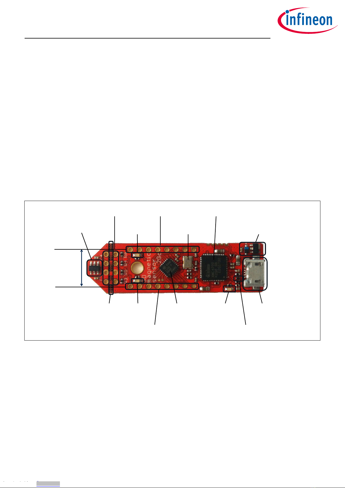
• The 3D evaluation board (EvalBoard) as shown in Figure 1, a ready-to-use printed circuit board (PCB) with
the 3D Hall sensor. The EvalBoard is based on the XMC2Go-Kit. More technical documents and detailed
description can be found at http://www.infineon.com/xmc2go.
• A standalone block magnet.
To use the 3D Magnetic Sensor 2 Go kit the user has to acquire a USB cable with a micro USB connection-end for
the EvalBoard side and a conventional USB connection for the PC side.
50mm
14mm
Figure 1 3D Magnetic Sensor 2 Go EvalBoard
1.2 Soware
The required soware to run the kit can be found at the Infineon web site. For further information refer to the
chapter Soware installation.
The soware package contains:
• A Graphical User Interface (GUI) for the user sensor evaluation.
• Firmware to be flashed into the XMC microcontroller for the low level communication with the sensor.
• USB driver J-Link from Segger which is necessary to establish the USB connection.
This soware was designed to be used with Windows 7 and Windows 10. It is compatible with both 32-bit and
64-bit system types. Other versions may also work, but have not been tested.
The USB protocols capabilities are defined by the Segger driver. Versions USB 2.0 and USB 3.0 should be
compatible.
The EvalBoard with the TLE493D-A2B6 3D Hall sensor can be used with the GUI version 3.0.0 and onwards.
The GUI is used to enable a communication between the sensor and the PC. The user can configure the sensor
to operate in dierent modes. In those modes the update rate of the magnetic field measured (X, Y and Z
components) and current consumption vary.
1.3 Magnet heads
As described in Chapter 1.1, a standalone magnet is provided with the 3D Magnetic Sensor 2 Go kit. This can be
manually placed to a desired position and then the magnetic field can be measured in the three dimensions.
3D Magnetic Sensor 2 Go - TLE493D-A2B6
Low Power 3D Hall Sensor with I²C Interface
Introduction
User Manual 3 1.0
2018-05-16
Downloaded from Arrow.com.Downloaded from Arrow.com.Downloaded from Arrow.com.

In addition, Infineon oers magnet heads which can be mounted on the EvalBoard. Currently two magnetic
heads are available, a joystick and a rotation knob.
Table 1 Magnet heads order codes
Magnet head for the 3D Magnetic Sensor 2 Go kit SP Number
Joystick SP001491834
Rotation knob SP001504602
Figure 2 Magnet heads for the 3D Magnetic Sensor 2 Go kit
The magnet used in the joystick magnet head is an axial magnetized magnet as shown in Figure 3. The magnet
material is ferrite, of class Y35, which is equivalent to a remanence of between 400 mT and 410 mT. The magnet
disk has a size of 5 mm diameter and 5 mm thickness. For more information about the magnet, please follow
this link: https://www.supermagnete.de/eng/disc-magnets-neodymium/disc-magnet-diameter-5mm-
height-5mm-neodymium-n45-nickel-plated_S-05-05-N
5 mm
5mm
Figure 3 Magnet used in the joystick magnet head
The magnet used in the rotate knob magnet head is a diametrically magnetized magnet as shown in Figure 4.
The magnet material is Neodymium Iron Boron (NdFeB) of class N45. The magnet is protected against corrosion
with Nickel coating (Ni-Cu-Ni). The magnet size is 4 mm diameter and 10 mm thickness. For more information
about the magnet, please follow this link: https://www.supermagnete.de/eng/rod-magnets-neodymium/rod-
magnet-diameter-4mm-height-10mm-neodymium-n45-nickel-plated_S-04-10-AN
3D Magnetic Sensor 2 Go - TLE493D-A2B6
Low Power 3D Hall Sensor with I²C Interface
Introduction
User Manual 4 1.0
2018-05-16
Downloaded from Arrow.com.Downloaded from Arrow.com.Downloaded from Arrow.com.Downloaded from Arrow.com.

4mm
10mm
Figure 4 Magnet used in the rotation knob magnet head
3D Magnetic Sensor 2 Go - TLE493D-A2B6
Low Power 3D Hall Sensor with I²C Interface
Introduction
User Manual 5 1.0
2018-05-16
Downloaded from Arrow.com.Downloaded from Arrow.com.Downloaded from Arrow.com.Downloaded from Arrow.com.Downloaded from Arrow.com.

2 EvalBoard description
The evaluation board (EvalBoard) is a ready-to-use printed circuit board (PCB) which contains:
• The 3D magnetic sensor TLE493D-A2B6. For the availability of 3D Magnetic Sensor 2 Go kits with dierent
sensor variants check the Infineon web page: https://www.infineon.com/cms/en/product/sensor/
magnetic-position-sensor/3d-magnetic-sensor/
• XMC1100 microcontroller based on ARM Cortex™-M0 at 48 MHz frequency connected to the 3D sensor.
• XMC4200 microcontroller based on ARM Cortex™-M4 at 144 MHz frequency used for the debugging and the
USB communication.
• Micro USB connector for power supply and communication with the Graphical User Interface (GUI).
• LED for indication of power supply and debugging.
• Two LEDs for user configuration.
• Voltage regulator, reverse current protection diode and ESD protection diode.
• Pin headers to access data lines (e.g. via oscilloscope, external microcontroller).
The dierent components and its location are shown in Figure 5. The 3D magnetic sensor can be separated
from the rest of the EvalBoard by cutting the break line.
pin header X3
user LED2
@P1.1
pin header X1
crystal for
debug IC
XMC4200 debug IC and
UART to USB bridge
voltage regulator and reverse
current protection diode
TLE493D-A2B6
mirco USB
connector
ESD protection
diode
power and
debug LED
XMC 1100
mircocontroller
pin header X2
user LED1
@P0.12
break
line
pin header
distance fits
to breadbord
Figure 5 Main components of the EvalBoard
2.1 Optional external power supply
The 3D Magnetic Sensor 2 Go EvalBoard is supplied via the USB cable. It is also possible to provide an external
power supply. If this is the case, a few considerations must be taken into account as described below.
The 3D Magnetic Sensor 2 Go EvalBoard must be supplied by external 5 Volt DC power supply connected to the
micro USB plug. The voltage regulator shis the voltage level to 3.3 V for the microcontrollers and the 3D
magnetic sensor. The Power & Debug LED indicates that the presence of the generated 3.3 V supply voltage.
Out of the box with the pre-programmed application and the on-board debugger in operation the EvalBoard
typically draws about 75 mA. This current can be delivered via the USB plug of a PC, which is specified to deliver
up to 500 mA. An on-board reverse current protection diode will ensure safe operation and protects the USB
port of the Laptop/PC in case power is provided through the pin header X1.
3D Magnetic Sensor 2 Go - TLE493D-A2B6
Low Power 3D Hall Sensor with I²C Interface
EvalBoard description
User Manual 6 1.0
2018-05-16
Downloaded from Arrow.com.Downloaded from Arrow.com.Downloaded from Arrow.com.Downloaded from Arrow.com.Downloaded from Arrow.com.Downloaded from Arrow.com.

It is not recommended to apply an additional power supply to the VDD pin of X1 (3.3 V) when the board is
powered via USB, because the 3.3 V supply could drive against the on-board power supply. The VDD pin can be
used to power an external circuit. But care must be taken not to draw more current than 150 mA, which is the
maximum current the on-board voltage regulator can deliver. Aer power-up the Debug LED starts blinking. In
case there is connection to a PC with correctly installed drivers, the Debug LED will turn from blinking to
constant illumination.
2.2 Pin header connector
The pin headers X1 and X2 can be used to extend the evaluation board or to perform measurements on the
XMC1100. The order of pins available at X1 and X2 corresponds to the pinning schema of the XMC1100
microcontroller in the TSSOP-16 pin package. The pinning table is also printed onto the bottom side of the PCB
(depending on the version). The pin header X3 can be used to access directly the 3D magnetic sensor pins.
X1
X2
X3
P0.5
P0.0
3.3 V
GND
P2.11
P2.10
P2.9
P2.7
P0.6
P0.7
P0.8
P0.9
P0.14
P0.15
P2.0
P2.6
VDD (P1.0)
GND
SDA (P2.10)
SCL (P2.11)
Figure 6 EvalBoard pin header connectors
The 3D Hall sensor pins can be accessed via the pin headers as shown in Table 2.
Table 2 Pin header description for the 3D magnetic sensor (X3)
TLE493D-A2B6 pin
number
Pin name
on board
XMC1100 port pin Sensor pin description
1 SCL P2.11 Interface clock and \INT pin, open drain
3 GND GND Ground pin
4 +3V3 P1.0 Supply pin
6 SDA P2.10 Interface data pin, open drain
The XMC1100 port pins P0.12 and P1.1 are connected the two user LEDs and are not available on the pin
headers.
Table 3 Pins used for the user LEDs
LED XMC1100 port pin
LED1 P0.12
LED2 P1.1
3D Magnetic Sensor 2 Go - TLE493D-A2B6
Low Power 3D Hall Sensor with I²C Interface
EvalBoard description
User Manual 7 1.0
2018-05-16
Downloaded from Arrow.com.Downloaded from Arrow.com.Downloaded from Arrow.com.Downloaded from Arrow.com.Downloaded from Arrow.com.Downloaded from Arrow.com.Downloaded from Arrow.com.

2.3 EvalBoard schematics
The schematics of the dierent blocks from the EvalBoard of the3D Magnetic Sensor 2 Go kit are provided in
this chapter. They can be used to design customized PCBs. The user (integrator) is responsible for the correct
functioning on system level as well as for the validation and testing.
Figure 7 EvalBoard schematic: 3D magnetic sensor
Figure 8 EvalBoard schematic: the voltage regulator (for the power supply)
3D Magnetic Sensor 2 Go - TLE493D-A2B6
Low Power 3D Hall Sensor with I²C Interface
EvalBoard description
User Manual 8 1.0
2018-05-16
Downloaded from Arrow.com.Downloaded from Arrow.com.Downloaded from Arrow.com.Downloaded from Arrow.com.Downloaded from Arrow.com.Downloaded from Arrow.com.Downloaded from Arrow.com.Downloaded from Arrow.com.

Figure 9 EvalBoard schematic: the LEDs for user configuration (connected to XMC1100 pins)
Figure 10 EvalBoard schematic: the XMC1100 microcontroller and pin headers
3D Magnetic Sensor 2 Go - TLE493D-A2B6
Low Power 3D Hall Sensor with I²C Interface
EvalBoard description
User Manual 9 1.0
2018-05-16
Downloaded from Arrow.com.Downloaded from Arrow.com.Downloaded from Arrow.com.Downloaded from Arrow.com.Downloaded from Arrow.com.Downloaded from Arrow.com.Downloaded from Arrow.com.Downloaded from Arrow.com.Downloaded from Arrow.com.

Figure 11 EvalBoard schematic: the Debug connection
3D Magnetic Sensor 2 Go - TLE493D-A2B6
Low Power 3D Hall Sensor with I²C Interface
EvalBoard description
User Manual 10 1.0
2018-05-16
Downloaded from Arrow.com.Downloaded from Arrow.com.Downloaded from Arrow.com.Downloaded from Arrow.com.Downloaded from Arrow.com.Downloaded from Arrow.com.Downloaded from Arrow.com.Downloaded from Arrow.com.Downloaded from Arrow.com.Downloaded from Arrow.com.
Este manual sirve para los siguientes modelos
1
Tabla de contenidos
Otros manuales de Accesorios de Infineon

Infineon
Infineon TLI4970 Instrucciones de montaje

Infineon
Infineon TLE5014P16 Manual de usuario

Infineon
Infineon TLI4970-D050T4 CurrentSense Shield2Go Manual de usuario

Infineon
Infineon TLI493D-A2B6 Manual de usuario

Infineon
Infineon XENSIV TLI4971 Instrucciones de funcionamiento

Infineon
Infineon SP37 Manual de instrucciones y seguridad

Infineon
Infineon TLE4997 Manual de usuario

Infineon
Infineon XENSIV BGT60TR13C Manual de usuario

Infineon
Infineon TLE5501 Series Manual de usuario


