User Manual
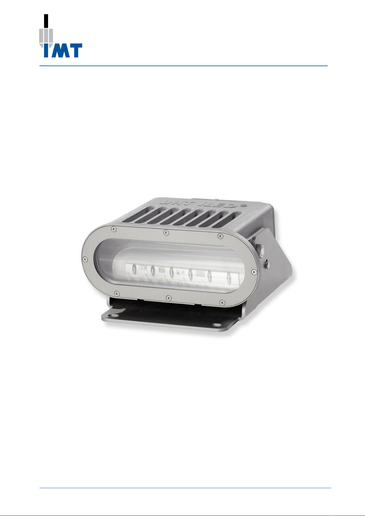
ILED Aquarius Floodlight
901.043.02 User Manual ILED Aquarius Floodlight 7 Version 2.1 201603
6. Installation
6.1 Preparation
1. Check whether the light fitting is to be installed in an environment that meets the ambient temperatures,
gas group and temperature class. This data is included on the light fitting type plate.
Installation of a light fitting in an environment that does not meet the specified
conditions may result in a dangerous situation.
Installation of a light fitting in an environment that does not meet the specified
ambient temperatures may have a negative effect on the useful life of the light
fitting.
2. Choose the correct type of protection for the light fitting. When doing so, ensure:
a. The choice of cut-off current for the safety device is suitable for the expected nominal current.
This depends on the number of light fittings that are connected.
b. The safety device's cut-out power is suitable for the maximum short-circuit current that the mains
power supply can provide.
6.2 Assembly
1. Remove the light fitting from the packaging.
2. Inspect the light fitting for mechanical damage.
3. Mount the light fitting to the construction.
Ensure there is a reliable connection to the earthing system, both with the external earthing point and
with the connection in the light fitting junction box. Take precautions to prevent corrosion to ensure
the functionality of the earth connection.
Ensure that the cable gland is suitable for the dimensions of the type of cable that will be connected
and has an IP level of IP66, IP67 or IP68 and in case of an explosion proof lighting fixture, is certified
according to EX e IIC T4 Gb and Ex tb IIIC T135C Db IP66 ( ATEX II2 GD) IEC 60079-0:2007 Ed 5,
IEC 60079-7 Ed 4, IEC 60079-31:2008 Ed 1.This is necessary to ensure the IP protection, and to be
suitable for a hazardous environment.
During assembly, make sure the light fitting is not subjected to mechanical stress.
4. Cable glands and blind plugs need to be installed according to the instructions of the manufacturer. This is
necessary to guarantee IP protection. The cable entries are M20x1.5 or M25x1.5.
Cables shall be stripped according to the instructions of the manufacturer with the appropriate tools to
guarantee the properties of the cable. Wire sleeves suitable for the quadratic wire diameter shall be placed
at the bare wire ends and fixed with a specified tool according to the instructions of the manufacturer.
5. Cut the cable to the required length.
6. Connect the cable to the terminals. The standard terminals in the junction box are suitable as a standard for
a core diameter of 0 - 4 mm².
7. Check the connections that have been made.
8. Close the junction box.
The installation must be carried out in accordance with IEC 60079-14.
WARNING
The installation must be carried out in conformance with (NEN-EN) IEC 60079-14.