10
MASONRY 350 F
IMER INTERNATIONAL S.p.A. GB
GB
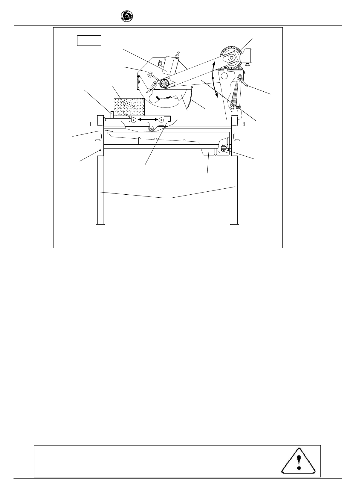
9. TRANSPORTATION (fig. 4)
- WARNING! Before moving the saw, lock head
support carriage movement by means of the relative knob
(Ref. 11, fig. 1). Remove the plug from the power socket.
To transport the machine use slinging equipment with 4
rope legs, fixing the hooks to the relative attachments.
10. INSTALLATION (Fig. 4)
Lift the machine out of its package and fix the hooks to the
relative attachments on the machine.
- Unlock the legs by sliding out pins (ref.1).
-Lock thelegsat workingheight.Refitthe pinsinthe legsupports.
- Install the machine on a completely even and stable surface.
- Release the carriage from the lever that secures it to the frame.
11. ELECTRICAL CONNECTION
- Ensure that there is an overload cutout device
fitted up-line on the power line.
- Ensure that the mains voltage corresponds to that specified
for the machine: 230V/50Hz - 110V/50Hz. The electrical power
cable must be suitably sized to avoid voltage drops. Cable
drums must not be used.
Connect the machine to an efficient earthing system.
The size of the power cable wires must be based on operating
current and length of the power line to prevent excessive
voltage drops (ref.Table 3).
Cables used on construction sites must be fitted with suitable
external sheathing that is resistant to wear, crushing and
extreme weather conditions (for example H07RN-F).
- All power supply installations must comply with
CEI 64-8 standards (harmonised document CENELEC
HD384).
12. MACHINE START-UP
Before connecting the machine to the power supply:
1 - Ensure that the metal structure is connected to an earthing
plant as indicated in Section 7 “Safety Precautions”.
2 - Ensure that the tank contains sufficient cooling water.
3 - Ensure that the power circuit corresponds to the requirements
as indicated in Section 11 “Electrical connections”.
- RESIDUAL CURRENT CIRCUIT PROTECTION
(KIT 230V-P/N.1169245 ; KIT 110V-P/N.1169249):
It’s obligatory to fit the saw with the differential switch
kit P/N 1169249 on the feeding cable(ref.3, fig.7).
To start up the saw, press the green ON key on the RCCB
switch and an orange led illuminates (RCCB protection on).
RESIDUAL CURRENT CIRCUIT BREAKER TEST:
Press the black key TEST on the RCCB; the switch
disconnects and the orange led turns off.
After performing the TEST, press the ON key again to activate
theRCCB.
- Carry out the RCCB TEST before each machine
start-up.
4 - Connect the machine to the power supply
5 – Press the black switch (Ref.7, fig.1) after ensuring that
cooling water reaches the blade: adjust the flow of cooling water
by turning the cock next to the blade guard (do not perform
cutting without water).
6 - Check that the direction of blade rotation corresponds to that
indicated by the arrow on the blade guard.
7 - If all is in order, proceed with cutting.
13. EMERGENCY STOP
- In an emergency, stop the machine by pressing the
stop control switch.
- The motor is fitted with an overload cutout device.
If the motor overheats, it will automatically shut down.
Allow the motor to cool and press the black switch on the
overload cutout device to restart (Ref. 7, fig. 1).
- The motor is protected against automatic re-start
after interruptions due to power failure. To resume
operation, when power is re-connected, press the black
switch on the overload cutout device (Ref. 7, fig. 1).
14. BLADE INSTALLATION (Fig.5)
By means of a hex wrench no.10, loosen the 3 screws that secure
the blade guard (Ref. 3). Using a hex wrench no. 13, loosen the
screw that secures the flanges on the blade: this screw has a
left-hand thread (rif.1). Remove the mobile flange (rif.2) and check
that the flanges, disc shaft and blade are not damaged.
- Never use worn blades.
- Only use blades that are designed for the number
of revolutions indicated on the machine rating plate.
- Check that blade rotation corresponds to that
indicated on the blade guard.
Centre the blade against the fixed flange, position the mobile
flange and tighten the securing screw by means of a hex
wrench no. 13 (turn clockwise). Return the guard to its original
position, locking the 3 screws (Ref. 3).
- Ensure that the blade guard (Ref.3) is locked
securely into position.
- WARNING! An incorrectly installed blade or a
screw insufficiently tightened can provoke damage to
the machine or injury to persons.
- Note that the blade must have an
external diameter of 350 mm., a central
hole diameter of 25.4 mm and max.
thickness of 3 mm.
- Check that the blade to be used is
suitable for the material to be cut.
- Do not use blades for wood! (fig. 6).
15. USE
- Leave a space of 150 cm around the machine to ope-
rate in full safety.
-Donotallowotherpersonstoapproachthemachineduringcutting.
- Never use the machine in fire-risk areas. Sparks can cause fire or
explosions.
- Make sure that the machine is switched off before positioning or
handling.
- Always ensure that the blade is free of any contact before start-
up. - Ensure correct installation of all protective devices.
Before starting work, fill the water tank. Top up during operation
whenever necessary: N.B. the pump suction hose must
always remain immersed in water.
- Insert the plug in the power socket.
- WARNING! For safety purposes the removal of
protective guards from the machine is strictly prohibited
The machine is protected against overload: this protection
triggers stopping the machine, after which the time necessary
for the overload to cool must pass before it is possible to
restart the machine.
- WARNING! Always switch off the machine before
carrying out blade adjustment.
15.1 VERTICAL BLADE MOVEMENT
To raise or lower the blade, slacken the support locking handle
turning it anti-clockwise (Ref. 11, fig. 1). The blade support (Ref. 4,
fig.1) remains free to rotate, so it can be secured in the desired
position, fully tightening the handle (ref. 11, fig. 1).
- Ensure that the locking handle is tightened fully before
starting work.
15.2 BLADE POSITIONING FOR 45° CUTS
To makea cut at 45°, the 45° support on the carriage is necessary.
Oncetheworkpieceiscorrectlypositioned,cuttingcanbegin,starting
the electric motor.
15.3 CUTTING
For safe use of the machine when cutting, push the carriage
forwards as the cut advances, placing your hands to the two
sides of the carriage. Never push directly on the piece to be cut.
Fig. 6