IMAGO VisionDevice Manual de usuario

Manual
VisionDevice – Industrial DashCam 1 000
Version 1.0 – August 2023

Contents Page 2 / 31
IMAGO Technologies GmbH
Strassheimer Str. 45; 61169 Friedberg; Germany; Tel. +49(0)6031-6842611
info@imago-technologies.com; www.imago-technologies.com
Contents
1 Handling and Safety Instructions ............................................................ 4
2 Introduction ................................................................................................. 5
Main features ...................................................................................................................... 6
3 Operating Conditions ................................................................................. 7
4 Interfaces ..................................................................................................... 8
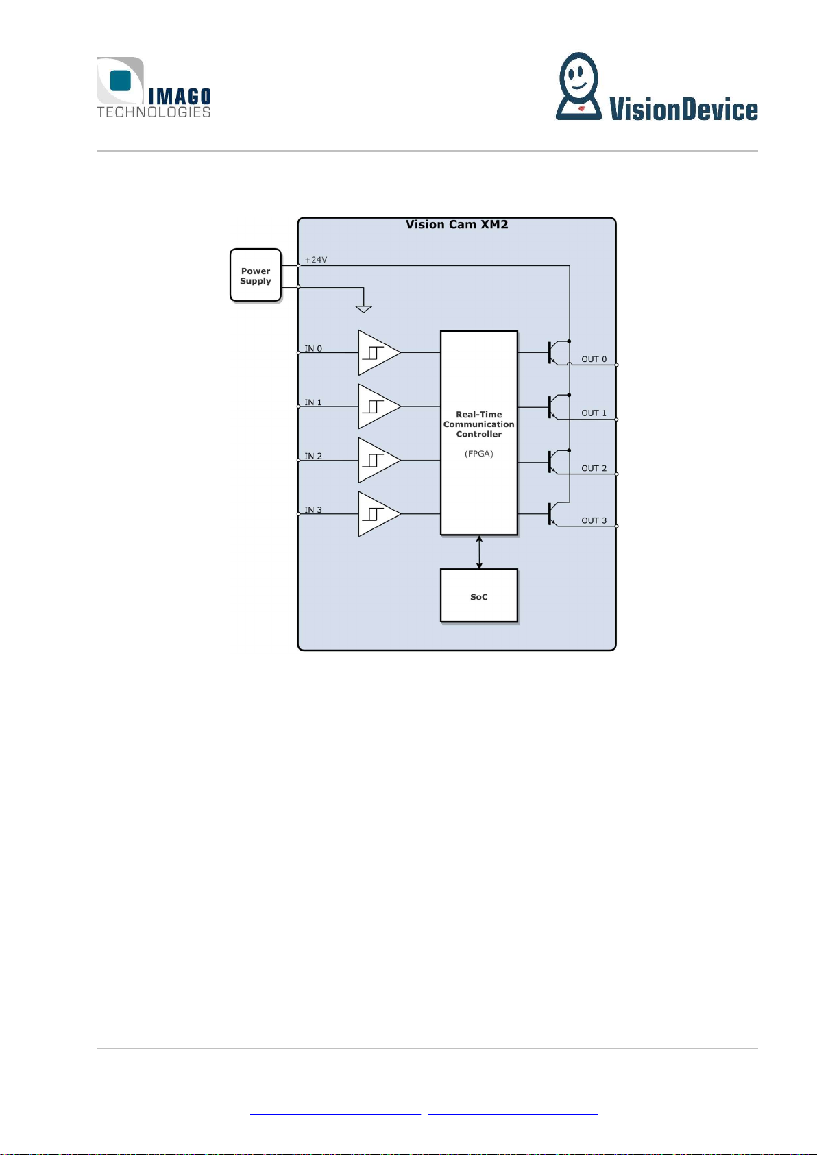
Power and I/O ..................................................................................................................... 8
4.1.1 Digital I/Os ......................................................................................................................................... 9
1 Gbit/s Ethernet M12 ...................................................................................................... 10
Status LEDs ...................................................................................................................... 10
5 Mechanical Drawings ................................................................................ 11
6 Web Based Graphical User Interface (WebGUI) ................................... 12
Overview ........................................................................................................................... 12
Accessing the GUI ........................................................................................................... 12
Welcome Page .................................................................................................................. 12
6.3.1 Indicator bar .................................................................................................................................... 14
6.3.2 Navigation panel ............................................................................................................................. 14
Event Log .......................................................................................................................... 15
View Live Page ................................................................................................................. 16
Configuration Page .......................................................................................................... 18
6.6.1 Setting IP-address and Web-Service Port .................................................................................. 19
6.6.2 Language and System Name ........................................................................................................ 19
6.6.3 Synchronize Time ........................................................................................................................... 19
6.6.4 Camera Settings ............................................................................................................................. 20
6.6.5 Setting Area of Interest.................................................................................................................. 21
6.6.6 Setting Encoder Bitrate and FPS ................................................................................................. 22
6.6.7 Setting Recording mode and video length ................................................................................ 22
6.6.8 Set triggering options .................................................................................................................... 23
View Video page............................................................................................................... 25
6.7.1 Viewing a Video – Simple player.................................................................................................. 26
6.7.2 Viewing a Video – Advanced ........................................................................................................ 27

Contents Page 3 / 31
IMAGO Technologies GmbH
Strassheimer Str. 45; 61169 Friedberg; Germany; Tel. +49(0)6031-6842611
info@imago-technologies.com; www.imago-technologies.com
About Page ........................................................................................................................ 28
Exit page ............................................................................................................................ 29
7 Support ....................................................................................................... 30
8 History ......................................................................................................... 31

1 Handling and Safety Instructions Page 4 / 31
IMAGO Technologies GmbH
Strassheimer Str. 45; 61169 Friedberg; Germany; Tel. +49(0)6031-6842611
info@imago-technologies.com; www.imago-technologies.com
1 Handling and Safety Instructions
Depending on the operating conditions, the housing temperature can exceed
60 °C. There is a risk of injury!
Caution! LED risk group 2. Do not look directly into the LED flash!
EMC conformity according to EN/IEC 61000-6-2:2005 is qualified for cable
lengths ≤ 30 m.
Electrical installation should be executed without power applied to the device
and all connected devices.
Please take special note of the voltage range which may be applied to the device.
Otherwise, permanent damage to the device may result!
Due to the characteristics and physical principles inside flash memory, memory
cards have a finite lifetime dictated by the number of write operations.
Therefore, take care of the regular write operations to prevent an early flash
damage.

2 Introduction Page 5 / 31
IMAGO Technologies GmbH
Strassheimer Str. 45; 61169 Friedberg; Germany; Tel. +49(0)6031-6842611
info@imago-technologies.com; www.imago-technologies.com
2 Introduction
Even in perfect machines, unwanted situations occur from time to time, which lead to machine downtime
and thus to loss of production. It is crucial to know what exactly have led to the downtime for avoiding the
sequence of events next time. Often, observing a working machine by a naked eye does not bring much due
to the speed of the machine. Moreover, sometimes it is impossible or even dangerous. For such cases
IMAGO has developed the VisionDevice – Industrial DashCam 1 000(VD-IDC).
The Industrial DashCam 1 000 is a surveillance and remote monitoring camera for industrial environments
in a match box form factor. The concept is similar to a dash-cam, adapted for industrial environments. In-
dustrial DashCam continuously monitors a scene without storing anything. Upon an event, which can be
defined by the user, the Industrial DashCam saves the video on to local storage media. The length of the
video as well as its span in time before and after the event can be defined by user. There are three types of
possible events: it can be a hardware trigger, absence of a heartbeat or changes in image. The Industrial
DashCam offers two digital inputs for the events. Furthermore, the Industrial DashCam is equipped with a
powerful internal LED lighting unit (S-Mount only), which is perfect for difficult lighting conditions.
This document is the manual of the Industrial DashCam. Hardware related aspects as well as the WebGUI
operation are described.

2 Introduction Page 6 / 31
IMAGO Technologies GmbH
Strassheimer Str. 45; 61169 Friedberg; Germany; Tel. +49(0)6031-6842611
info@imago-technologies.com; www.imago-technologies.com
Main features
18 - 30 V DC power supply
Passive cooling without heat sink
Image sensors:
o 2560 × 2048 pixels
o Global shutter
o Monochrome or
Lens:
o C-Mount
Internal LED lighting:
o Controllable via software
o Automatic current regulation
Recording:
o Web-GUI available via the IP-address of the device
o File Format: MPEG4 (H.264)
o Frame rate: 1048 × 600: = 1133 fps
1200 × 680: = 1000 fps
1400× 1400: = 436 fps
o Recording time: ≤ 10 s (past, future or a mix of both)
o Mass storage 32 GB
o Trigger Modes:
Regular: Video is recorded when the digital input signal raises
Heartbeat: Video is recorded when the Heartbeat signal is lost
Software: Recording is started after a threshold of change is reached within a ROI
o Recording modes:
History: Video prior to the trigger event is saved
Future: Video after the trigger event is saved
Mixed: Video prior and after the trigger event is saved
Digital inputs / outputs:
o 4x digital output
o 4x digital input
Ethernet interface 1000 Mbit/s
Housing:
o 18 - 30 VDC power supply
o Passive cooling without heat sink

3 Operating Conditions Page 7 / 31
IMAGO Technologies GmbH
Strassheimer Str. 45; 61169 Friedberg; Germany; Tel. +49(0)6031-6842611
info@imago-technologies.com; www.imago-technologies.com
3 Operating Conditions
Power Supply:
Parameter Min. Typ. Max. Unit
Supply voltage 18 24 30 V
Supply current (@24V) A
Digital Input:
Parameter Min. Typ. Max. Unit
Input voltage range 0 25 V
Rising edge threshold voltage 7.4 9.4 V
Falling edge threshold voltage 4.7 6.3 V
Input resistance 15.5 k
Digital Output:
Parameter Min. Typ. Max. Unit
Output current 50 mA
Output high voltage VSupply - 0.2 V
Environment:
Parameter Value Unit
Weight, including cable g
Operating temperature °C
Operating humidity, relative, non-condensing %
Storage temperature -10 … +70 °C
Storage humidity, relative, non-condensing 5 … 95 %

4 Interfaces Page 8 / 31
IMAGO Technologies GmbH
Strassheimer Str. 45; 61169 Friedberg; Germany; Tel. +49(0)6031-6842611
info@imago-technologies.com; www.imago-technologies.com
4 Interfaces
Power and I/O
A 17-pin M12 A-coded male connector is used for power supply and I/O signals.
Pin Number Function
1 GND (supply and I/O)
2 Power supply (+24 V)
3 RS-232 TX
4 RS-232 RX
5 Digital IN0
6 Digital IN1
7 Digital IN2
8 Digital OUT0
9 Digital OUT1
10 Digital OUT2
11 Digital OUT3
12 Digital IN3
13 USB D+
14 USB D-
15 Reserved
16 Reserved
17 VBUS (+5 V output)
We recommend using shielded cables, for example:
Length Product IMAGO
order code
1.5 m Phoenix contact 1430284 “SAC-17P- 1,5-35T/FS SH SCO” 10004440
3 m Phoenix contact 1430297 “SAC-17P- 3,0-35T/FS SH SCO” 10004441
5 m Phoenix contact 1430307 “SAC-17P- 5,0-35T/FS SH SCO” 10004442
There are also angled and solder versions available.

4 Interfaces Page 9 / 31
IMAGO Technologies GmbH
Strassheimer Str. 45; 61169 Friedberg; Germany; Tel. +49(0)6031-6842611
info@imago-technologies.com; www.imago-technologies.com
4.1.1 Digital I/Os
The following illustration shows the electrical equivalent circuit for the digital input and output signals:
Figure 1: Simplified digital I/O circuit
The input signals use a Schmitt trigger circuit with the power supply GND as voltage reference.
The digital output circuit uses open-emitter configuration. All outputs are internally supplied by the 24V
power input.

4 Interfaces Page 10 / 31
IMAGO Technologies GmbH
Strassheimer Str. 45; 61169 Friedberg; Germany; Tel. +49(0)6031-6842611
info@imago-technologies.com; www.imago-technologies.com
1 Gbit/s Ethernet M12
The Vision Cam uses an 8-pin M12 X-coded female connector for Ethernet.
Pin Number Function
1 D1+
2 D1-
3 D2+
4 D2-
5 D4+
6 D4-
7 D3-
8 D3+
We recommend using shielded cables, for example:
Length Product IMAGO order code
1 m Phoenix contact 1407471 “NBC-MSX/ 1,0-94F/R4AC SCO” 10007049
2 m Phoenix contact 1407472 “NBC-MSX/ 2,0-94F/R4AC SCO” 10007050
5 m Phoenix contact 1407473 “NBC-MSX/ 5,0-94F/R4AC SCO” 10008076
Status LEDs
The meaning of each status LED and its color is listed in the tables below.
LED Color Function
Green Ethernet link is up
Red Ethernet activity
Green Power On
Green
blinking USB recovery mode
Red Power off
U0 Green User LED 0
U1 Green User LED 1
U1
U0
Tabla de contenidos


