IKONNIK KA-6 Manual

Owner’s Manual &
Technical Information

2
Specication
• Advanced 2.4GHz 6-channel transmitter
• Lightweight, full-range 6 channel receiver
• Uses the acclaimed Hitec Red protocol
• Simple, auto-pairing
• Servo reverse on all four primary channels
• Switched channel 5 and 6
• Mode 1 / Mode 2 selectable
• Delta mixing available
• Digital trims
• Adjustable stick length
• Adjustable stick tension
• Low consumption 4 cell (4.8V) transmitter
• Charging jack for optional rechargeable battery upgrade
• Simulator socket

3
Contents
Introduction ................................................................................ 4
Hitec 2.4GHz technology ........................................................... 4
Vibration ..................................................................................... 5
Receiver antenna installation ................................................... 5
Handling connectors .................................................................. 5
Installing batteries in the transmitter ....................................... 6
Turning on the KA-6 transmitter ................................................ 6
Transmitter aerial orientation .................................................... 7
Stick length adjustment ............................................................. 7
Stick lever tension adjustment .................................................. 7
Pairing ....................................................................................... 10
Failsafe .....................................................................................11
Servo reverse............................................................................11
Trim adjustment .......................................................................11
Elevon (Delta) mix ....................................................................11
Warranty, support and service ................................................12
IMPORTANT! This radio control system is not a toy. It must be operated
according to these instructions and may cause serious injury to persons
or damage to property if not used responsibly or if operated without due
caution. Unsuitable for children under 14 years of age.

4
Introduction
Thank you for purchasing the advanced IKONNIK KA-6 2.4GHz radio control
system. It is designed for operating small to medium size model aircraft and
features a lightweight, full-range receiver.
Its uncomplicated design makes it the perfect rst or second radio system for
the sport modeller.
The transmitter and receiver use state of the art manufacturing processes.
The receiver features dual diversity aerials for extra security and that
important ‘locked-in’ feeling.
Identifying your transmitter’s features and function switches:
Channel 6 Switch
Elevator/Aileron
Control Stick
Elevator Trim
Aileron Trim
ON/OFF Switch
Delta/Elevon Mix
Switch
Servo Reversing
Switches
Rudder Trim
Throttle/Rudder
Control Stick
Throttle Trim
Channel 5 Switch
Power LED
Mode 1/Mode2
Switch
Neck
Strap
Eyelet
Hitec 2.4GHz technology
Hitec Red technology is trusted by pilots worldwide to provide a supremely
reliable and responsive radio link. Incorporating Hitec’s AFHSS (Adaptive
Frequency Hopping Spread Spectrum) technology, Hitec Red offers a
simple, cost-effective solution for pilots looking to y any model from the
growing range of Hitec Red enabled aircraft from Ares. Pair to Fly with total
condence.
Pair to Fly
5
Vibration
The receiver contains precision electronic parts. Ensure that you avoid
vibration, shock, and temperature extremes. For protection, wrap the receiver
in foam rubber, or use some other vibration-absorbing material.
If you are ying near water, it’s also a good idea to protect the receiver by
placing it in a plastic bag and securing the open end of the bag with a rubber
band before wrapping it with foam.
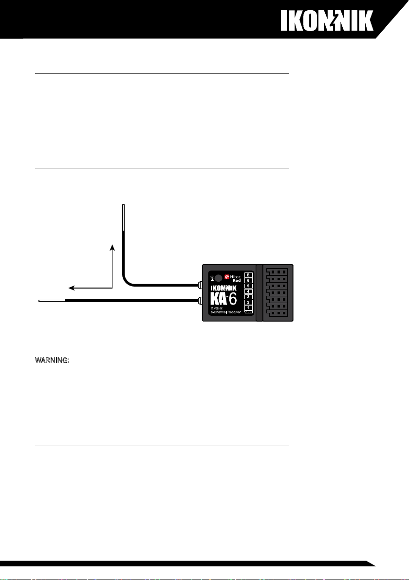
Receiver antenna Installation
The KA-6 receiver has two aerials for maximum security. Please install as
shown:
F/S
B
6
5
4
3
2
1
2.4GHz
6-Channel Receiver
90°
WARNING: Never pinch or bend the antennas. Avoid locating the antennas
next to any components that are likely to create interference such as
batteries, motors, ESCs etc. Avoid locating the antennas in highly conductive
environments such as carbon ber fuselages etc.
Never change the length of the antennas. Cutting the length of either
antenna will seriously affect the receiver’s range.
Handling connectors
Always ensure that you maintain the correct polarity when connecting a servo
or battery connector to the receiver. When unplugging connectors from the
receiver, ensure you hold the plastic connector and do not pull directly on the
wires.

6
Installing batteries in the transmitter
Remove the transmitter battery cover and insert four AA alkaline cells (not
included) taking care to observe the correct polarity. Re-t the battery cover
You can use rechargeable batteries in the KA-6 transmitter. Ensure that
you maintain the correct polarity. If using rechargeable batteries, they may
be charged using a suitable, compatible charger and the factory-installed
charging socket on the right-hand side of the transmitter. While individual
rechargeable batteries can be used in the battery box, we recommend using
a welded pack that connects to the factory-installed socket in the battery
compartment. Simply remove the upper battery springs before installing the
battery pack.
WARNING: Do not attempt to charge non-rechargeable batteries. Never mix
rechargeable batteries with non-rechargeable alkaline batteries. Do not mix
old and new batteries. Do not fast charge batteries when installed in the
transmitter as this may lead to overheating which can result in damage to the
batteries and the transmitter and even result in re.
Turning on the KA-6 transmitter
The transmitter is turned on using the switch located on the front. Always
switch on the transmitter rst, followed by the receiver. Push the switch
forward to turn on the transmitter. The LED will illuminate red.
ON Switch

7
Transmitter aerial orientation
In use, the optimum operating range of the transmitter is achieved with the
aerial in the upright forward-facing position. Do not point the aerial directly at
the model.
Stick length adjustment
As everyone’s hand size is different, the KA-6 transmitter uses a two-piece
stick top that can be adjusted in length to suit a variety of different users’
hand size.
Separate the two parts of the stick top by holding the lower part stationary
and unscrewing the upper part. Once the stick top is in the correct position,
it can be locked in place by tightening the bottom section of the stick.
Stick lever tension adjustment
The stick spring tension can be adjusted to suit the exact stick ‘feel’ you wish.
To carry out this procedure, you must remove the rear of the transmitter case.
Start by switching off the transmitter and remove the batteries. Now remove
the six self-tapping screws that hold the rear of the case in position and store
safely.
Place the transmitter face down on a soft surface (sponge rubber is perfect
for this). Gently ease off the rear of the transmitter case taking care to ensure
that the wiring loom between the charging socket and the battery box is not
disturbed.
Using a small Philips screwdriver, rotate the adjusting screw for each stick to
give the desired spring tension. The tension decreases when the adjusting
screw is turned counterclockwise, and increases when turned clockwise.

8
When you are happy with the stick spring tension, you may carefully reinstall
the rear cover ensuring that you haven’t trapped any wires. Replace the six
self-tapping screws taking care not to over-tighten.
Changing the transmitter to Mode 1
As standard, the transmitter is factory-congured to Mode 2 (with the throttle
on the left hand stick). The transmitter can be changed to Mode 1 (with the
throttle on the right hand stick).
MODE 1
Throttle
High
Throttle
Low
Down
Elevator
Up
Elevator
Left
Aileron
Right
Aileron
Left
Rudder
Right
Rudder
MODE 2
Throttle
High
Throttle
Low
Down
Elevator
Up
Elevator
Left
Aileron
Right
Aileron
Left
Rudder
Right
Rudder
MODE 1
Throttle
High
Throttle
Low
Down
Elevator
Up
Elevator
Left
Aileron
Right
Aileron
Left
Rudder
Right
Rudder
MODE 2
Throttle
High
Throttle
Low
Down
Elevator
Up
Elevator
Left
Aileron
Right
Aileron
Left
Rudder
Right
Rudder

9
1. Remove the six self-tapping screws that retain the rear of the transmitter
case.
2. Place the transmitter face down on a soft surface.
3. Gentle ease off the rear of the transmitter case.
4. Remove the throttle ratchet from the back of the right hand stick unit by
removing the two retaining screws.
5. Re-t the throttle ratchet to the left hand stick unit and retain with the two
retaining screws.
6. Enable the elevator spring tension by removing the single screw shown in
the diagram.

10
7. Transfer this screw to the other stick unit to disable the spring tensioner.
8. Check the operation of the throttle stick and once happy, ret the rear of
the transmitter case.
9. Re-t the six self-tapping screws taking care not to over-tighten.
10. Now move the mode selection switch to the Mode 1 position.
Connection Diagram
Use these diagrams to connect the KA-6 for I.C. and electric powered aircraft.
Switch to
MODE 1
F/S
B
6
5
4
3
2
1
2.4GHz
6-Channel Receiver
F/S
B
6
5
4
3
2
1
2.4GHz
6-Channel Receiver
Otros manuales para KA-6
1
Tabla de contenidos
Otros manuales de Mando a distancia de IKONNIK


