
IDENTEC SOLUTIONS i-MARK 3 Instrucciones de montaje

Rhein Tech Laboratories, Inc. Client: Identec Solutions Inc.
360 Herndon Parkway Model Name: i-Mark 3
Suite 1400 Standards: FCC 15.209/IC RSS-210
FCC/IC ID: O2E-ILR-IM3/3538B-IM3Herndon, VA 20170
http://www.rheintech.com Report #: 2007198
Page 28 of 34
Appendix H: Manual
Please refer to the following pages.

i-MARK 2, i-MARK 3
Installation and Hardware Manual

i-MARKInstallation and Hardware Manual
Page 2 of 22
Proprietary Notice
This document contains confidential information proprietary to ID NT C SOLUTIONS and may not be
used or disclosed to other parties in whole or in part without prior written authorization from ID NT C
SOLUTIONS.
Disclaimer and Limitation o Liability
ID NT C SOLUTIONS AG and its affiliates, subsidiaries, officers, directors, employees and agents
provide the information contained in this Manual on an “as-is” basis and do not make any express or
implied warranties or representations with respect to such information including, without limitation,
warranties as to non-infringement, reliability, fitness for a particular purpose, usefulness,
completeness, accuracy or up-to-dateness. ID NT C SOLUTIONS shall not in any circumstances be
liable to any person for any special, incidental, indirect or consequential damages, including without
limitation, damages resulting from use of or reliance on information presented herein, or loss of profits
or revenues or costs of replacement goods, even if informed in advance of the possibility of such
damages.
Trademarks
“ID NT C SOLUTIONS”, “Intelligent Long Range”, “ILR” and the stylized “i” are registered trademarks
and “i-Q”, “i-D”, “i-B”, “i-CARD”, “i-PORT”, “i-LINKS”, “Solutions. It’s in our name.”, “Smarten up your
assets” are trademarks of ID NT C SOLUTIONS, Inc. and/or ID NT C SOLUTIONS AG.
Copyright Notice
Copyright © 2007 ID NT C SOLUTIONS. All rights reserved.
No part of this document may be reproduced or transmitted in any form by any means, photographic,
electronic, mechanical or otherwise, or used in any information storage and retrieval system, without
the prior written permission of ID NT C SOLUTIONS.
Reg. No. IM.0732. N
Order Code:
Issue 0 / June 2007
– 25. June 2007 –
ID NT C SOLUTIONS AG,
Millenium Park 2, 6890 Lustenau, Austria
Phone: +43 5577 87387- 0, Fax: +43 5577 87387-15
mail: [email protected]
www.identecsolutions.com
Subject to alteration without prior notice.
© Copyright ID NT C SOLUTIONS 2007
Printed in Germany

i-MARK Installation and Hardware Manual
Page 3 of 22
Radio Frequency Compliance Statement
ID NT C SOLUTIONS, Inc. is the responsible party for the compliance of the following devices:
MOD L: i-MARK 2 i-MARK 3
FCC ID: O2 -ILR-IM2 O2 -ILR-IM3
CANADA: 3538B-IM2 3538B-IM3
UROP : C 0678(!) C 0678(!)
The user(s) of these products are cautioned to only use accessories and peripherals approved, in
advance, by ID NT C SOLUTIONS, Inc. The use of accessories and peripherals, other than those
approved by ID NT C SOLUTIONS, Inc., or unauthorized changes to approved products, may void the
compliance of these products and may result in the loss of the user(s) authority to operate the
equipment.
Operation is subject to the following conditions: (1) these devices may not cause harmful interference,
and (2) these devices must accept any interference, including interference that may cause undesired
operation of the device.
FCC Compliance
This equipment has been tested and found to comply with the limits for a Class A digital device,
pursuant to Part 15 of the FCC Rules. These limits are designed to provide reasonable protection
against harmful interference when the equipment is operated in a commercial environment. This
equipment generates, uses, and can radiate radio frequency energy and, if not installed and used in
accordance with the instruction manual, may cause harmful interference to radio communication.
Operation of this equipment in a residential area is likely to cause harmful interference in which case
the user will be required to correct the interference at his/her own expense.
For FCC compliance, the supplied ferrite cores must be placed onto the driver loops where the leads
attach to the i-MARK 3.
Warning: Changes or modifications to this unit not expressly approved by the party responsible for
compliance could void the user’s authority to operate the equipment.
Industry Canada Compliance
This Class A digital apparatus meets all requirements of the Canadian Interference-Causing quipment
Regulations.
Cet appareil numérique de la classe A respecte toutes les exigences du Règlement sur le matériel
brouilleur du Canada.
European Noti ication according R&TTE Directive
This equipment complies to Art. 6.4 of R&TT Directive (1999/5/ C). It is tested for compliance with the
following standards:
N 300 220-1 V1.3.1 (2000-09), N 300 220-3 V1.3.1 (2000-09), TSI N 301 489 V1.4.1 (2002-08), TSI
N 301 489 V1.4.1 (2002-08)

i-MARKInstallation and Hardware Manual
Page 4 of 22
This product contains components that are sensitive to electrostatic discharges. Please observe the
special instructions for their protection. Incorrect handling can damage the unit and cause the
invalidation of the warranty.
Minimum sa ety precautions against electrostatic discharge:
•stablish earth contact before you touch the unit. For example, touch the earthing screw on the
unit. ven better: Use an antistatic ribbon and earth yourself permanently for the time you
handle the unit.
•Avoid unnecessary contact with the unit connectors and assemblies inside the unit.
•Only open the unit if the operational settings (as described in the manual) expressly require this.
•Use antistatic tools for the setting of the unit. (Warning: Do not touch life-threatening voltages
with these tools).
•Do not store unit and components without protective packaging.
•Only remove unit and components from the packaging immediately prior to installation.
These notes are not su icient to guarantee complete protection rom electrostatic
discharges! We recommend the use o suitable protective equipment.

i-MARK Installation and Hardware Manual
Page 5 of 22
Contents
1
SAFETY INSTRUCTIONS ...............................................................................................7
2
INTRODUCTION............................................................................................................9
2.1
P
R PARATIONS
...............................................................................................................9
2.2
S
COP OF
T
HIS
D
OCUM NT
...............................................................................................9
2.3
R
SPONSIBILITY
.............................................................................................................9
2.4
U
PDAT S
....................................................................................................................10
2.5
S
COP OF
D
LIV RY
—V
ISUAL
I
NSP CTION
..........................................................................10
2.6
A
SSOCIAT D
D
OCUM NTS
...............................................................................................10
2.7
B
LU TOOTH
M
ODUL
.....................................................................................................10
2.8
I
NT RNAL
M
AINS
S
UPPLY
................................................................................................10
3
INSTALLATION ...........................................................................................................11
3.1
M
CHANICAL
I
NSTALLATION
.............................................................................................11
3.1.1
i-MARK 2...................................................................................................................11
3.1.2
i-MARK 3...................................................................................................................12
3.2
L CTRICAL
I
NSTALLATION
..............................................................................................13
3.2.1
Safety Instructions.....................................................................................................13
3.2.2
Maximum Overall Cable Runs of Daisy Chain Cabling ...................................................13
3.2.3
Position of Ports ........................................................................................................13
3.2.4
Daisy Chain Connectors .............................................................................................14
4
INITIAL OPERATION ..................................................................................................15
4.1
G
N RAL
....................................................................................................................15
4.2
T
OOLS R QUIR D
..........................................................................................................15
4.3
C
ONFIGURATION
...........................................................................................................15
4.3.1
Adjusting the Inductive Loop Field ..............................................................................15
4.3.2
Adjusting the Inductive Loop Field ..............................................................................15
4.3.3
Operation Mode—Continuous/host only.......................................................................16
4.3.4
Operation Mode—Slave/master ..................................................................................16
4.3.5
Synchronization Mechanism........................................................................................16
4.3.6
Slot Configuration xamples.......................................................................................17
4.4
C
H CKING TH
I
NSTALLATION
..........................................................................................18
5
TROUBLESHOOTING ...................................................................................................19
5.1
G
N RAL
....................................................................................................................19
5.2
S
TATUS
D
ISPLAY
(L D
S
) ................................................................................................19
5.3
L
OOP
RROR
...............................................................................................................19
6
MAINTENANCE............................................................................................................20
6.1
G
N RAL
....................................................................................................................20
6.2
T
AG
B
ATT RY
L
IF
........................................................................................................20
6.3
P
R CAUTIONARY
M
AINT NANC
........................................................................................20
6.4
XCHANGING A MARK R WITHIN TH DAISY CHAIN
.................................................................20
6.5
S
PAR
P
ARTS
...............................................................................................................21
6.5.1
Recommended spare parts stock ................................................................................21
6.5.2
Preparing the spare parts...........................................................................................21
6.5.3
xamination and repair of exchanged parts.................................................................21
6.6
R
TURNS
....................................................................................................................21

i-MARKInstallation and Hardware Manual
Page 6 of 22
7
TECHNICAL SPECIFICATIONS ....................................................................................22
7.1
O
P RATING
D
ATA
.........................................................................................................22
7.2
L CTRICAL
D
ATA
.........................................................................................................22
7.3
M
CHANICAL
D
ATA
........................................................................................................22
7.4
NVIRONM NTAL
C
ONDITIONS
.........................................................................................22

i-MARK Installation and Hardware Manual
Page 7 of 22
1Sa ety Instructions
The system described in this manual is for exclusive operation by trained employees. Only qualified
personnel that know the potential dangers involved should perform the installation, settings,
maintenance and repair of the units used.
Operational Sa ety
The correct and safe use of these systems assumes that operating and service personnel follow the
safety measures described in the manual alongside the generally acceptable safety procedures.
If there is a possibility that safe operation cannot be guaranteed the system must be switched off and
secured against accidental use. Then the service unit responsible must be informed.
Sa ety Documents
This ILR system was designed, tested and supplied in perfect condition according to document I C348
Safety Requirements for lectronic Units of Class 1.
Condensate / Change o Temperature
Moving the systems from a cold to a warm environment could lead to dangerous situations due to
condensation. Therefore it must be ensured that the system can adjust itself to the warmer
temperature.
Do not open the housing
There is no need to open the housing in order to set any ILR unit. No unit has any internal setting
elements or displays. All settings are performed using software via the Service Interface.
Earthing
Before establishing any connections the housing of the system must be earthed.
Connections / Power Supply
The supply circuits must comply with the conditions set out for the S LV circuits (see N 60950).
The signal circuits must comply with the conditions set out for the S LV circuits (see N 60950).
Use screened cables for the power supply. This is the only way to achieve the prescribed MC.
During maintenance damage could occur if printed circuit boards or cables are connected or
disconnected whilst the power supply is still on. Therefore only work on the connection and the
components when they are not live.
Fuses
Only experts who are aware of the dangers involved may replace the fuses. It must be ensured that
only fuses of the required current rating and the correct type are used for replacement. The use of
repaired fuses and/or short-circuiting the fuse holders is prohibited.
Spare Parts
We recommend that only personnel, original products, spare and replacement parts authorized by
ID NT C SOLUTIONS be used for installation, service and repair. Otherwise ID NT C SOLUTIONS
does not accept any responsibility for materials used, work carried out or possible consequences.

i-MARKInstallation and Hardware Manual
Page 8 of 22
Electrostatic Discharge
Semi-conductors of the type MOS or CMOS as well as two-pin types and precision resistance are
sensitive to SD. All components, printed circuit boards and auxiliary systems should therefore always
be classed as sensitive to electrostatic discharge.
Before opening the cover the unit should be placed onto an SD-protected surface. As with all work on
modern electronic modules the use of SD clamps and SD mats during work on the unit is
recommended.
•Sufficiently protect all printed circuit boards that were removed from the unit from damage.
•Observe all normal precautions for the use of tools.
•Use SD-protected packaging material.
Never use measuring units with low impedance for measuring or testing systems with semi-conductor
components. Never use high voltage testing units or dielectric test units to test systems with semi-
conductor components.
If it is necessary to check the isolating properties of the field wiring, the assemblies (electronic units
and sensors) should be disconnected.
arth the test units.
ID NT C SOLUTIONS does not accept returns of products where the regulations concerning the SD
precautions and protective packaging materials were not followed.
SD – lectrostatic Discharge
MC – lectromagnetic Compatibility
S LV – Safety xtra Low Voltage – Protective measure against dangerous body currents, formerly: protective first voltage range
i-MARK Installation and Hardware Manual
Page 9 of 22
2Introduction
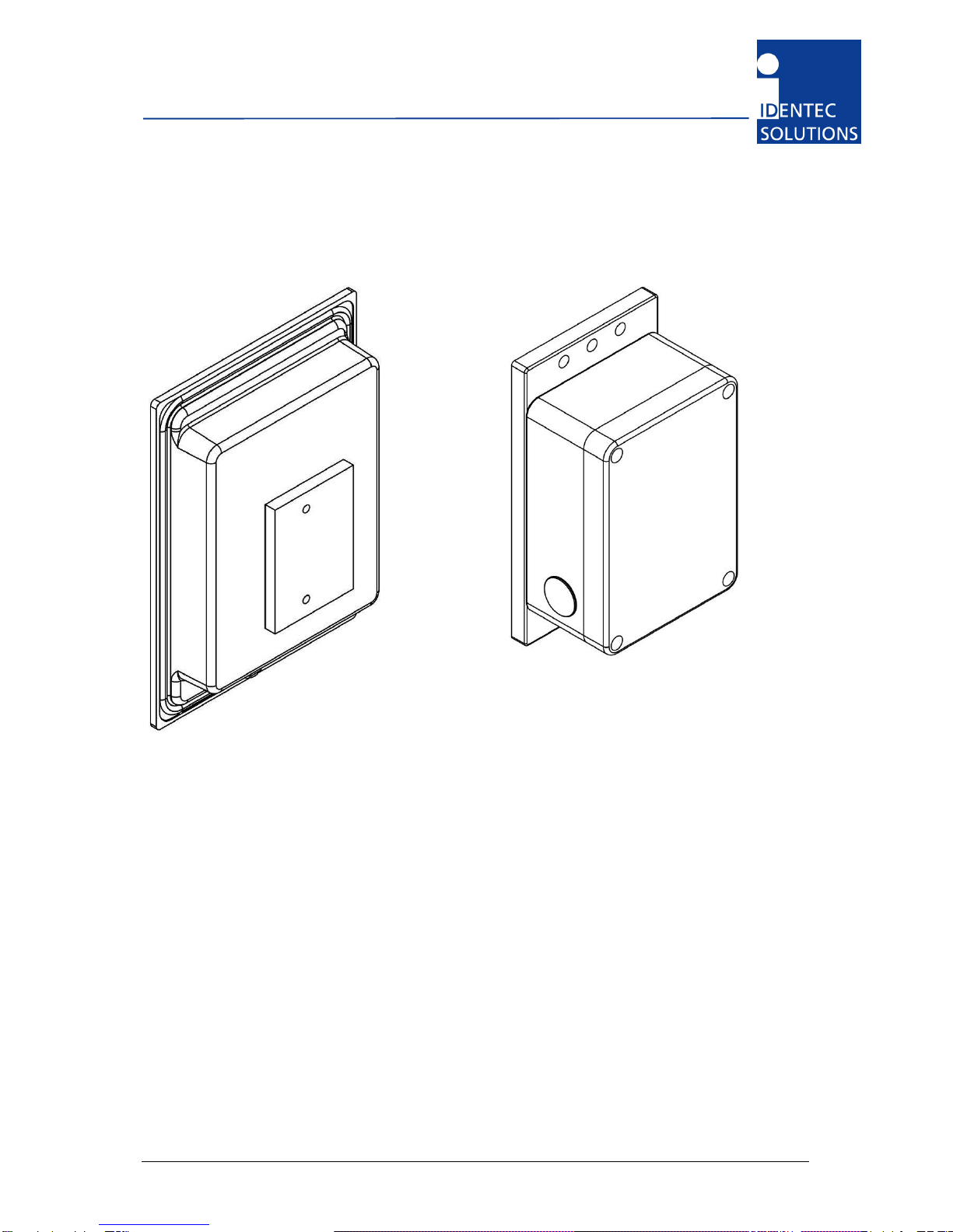
Compact Unit i-MARK 2
Central unit i-MARK 3
2.1 Preparations
This installation manual must be read carefully prior to starting the installation. The described
installation work assumes that installation materials like cable, antenna and data tag holder etc are
available
2.2 Scope o This Document
This document is the hardware description of both the i-MARK 2 and i-MARK 3. This document is
intended only for mechanical and electrical installation of this central units. A general system
description, especially of the Position Marker technology can be found in the extra system description;
please see below.
2.3 Responsibility
ID NT C SOLUTIONS is not responsible for any errors occurring in this document.
Este manual sirve para los siguientes modelos
1
Tabla de contenidos
Otros manuales de Otro de IDENTEC SOLUTIONS


