9
SE1L Safety Laser Scanner
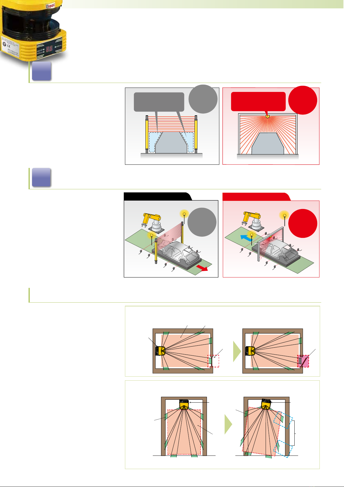
Warning Zone
The warning zone is a non-safety area and is connected to
WARNING 1 and 2 outputs.
When an object is detected within this zone, the WARNING
signal turns from ON to OFF. The warning signal can
be used as an alert signal to prevent humans or objects
approaching the protection zone. For moving applications,
warning zones can be used to reduce the speed of the
AGV to avoid collision.
Warning Zone 1
Warning Zone 2
OSSD
The OSSD signal is a safety signal. When humans are
detected inside the protection zone, the OSSD signal turns
from ON to OFF. Also the OSSD signal has a self-diagnosis
function that tests the signal periodically to detect
malfunction. The OSSD signal will turn OFF when a error is
detected due to the self-diagnosis function.
xThe OSSD is a safety signal and should be
connected directly to a force guided relay or a
device that controls the machine or AGV.
xWhen setting the response time of the OSSD
signal, provide sufficient time to stop operation
of the machine or AGV.
xThe operator must test to make sure the settings
are properly configured before operation.
Note: The signal is 24V when the OSSD signal is ON and 0V when OFF.
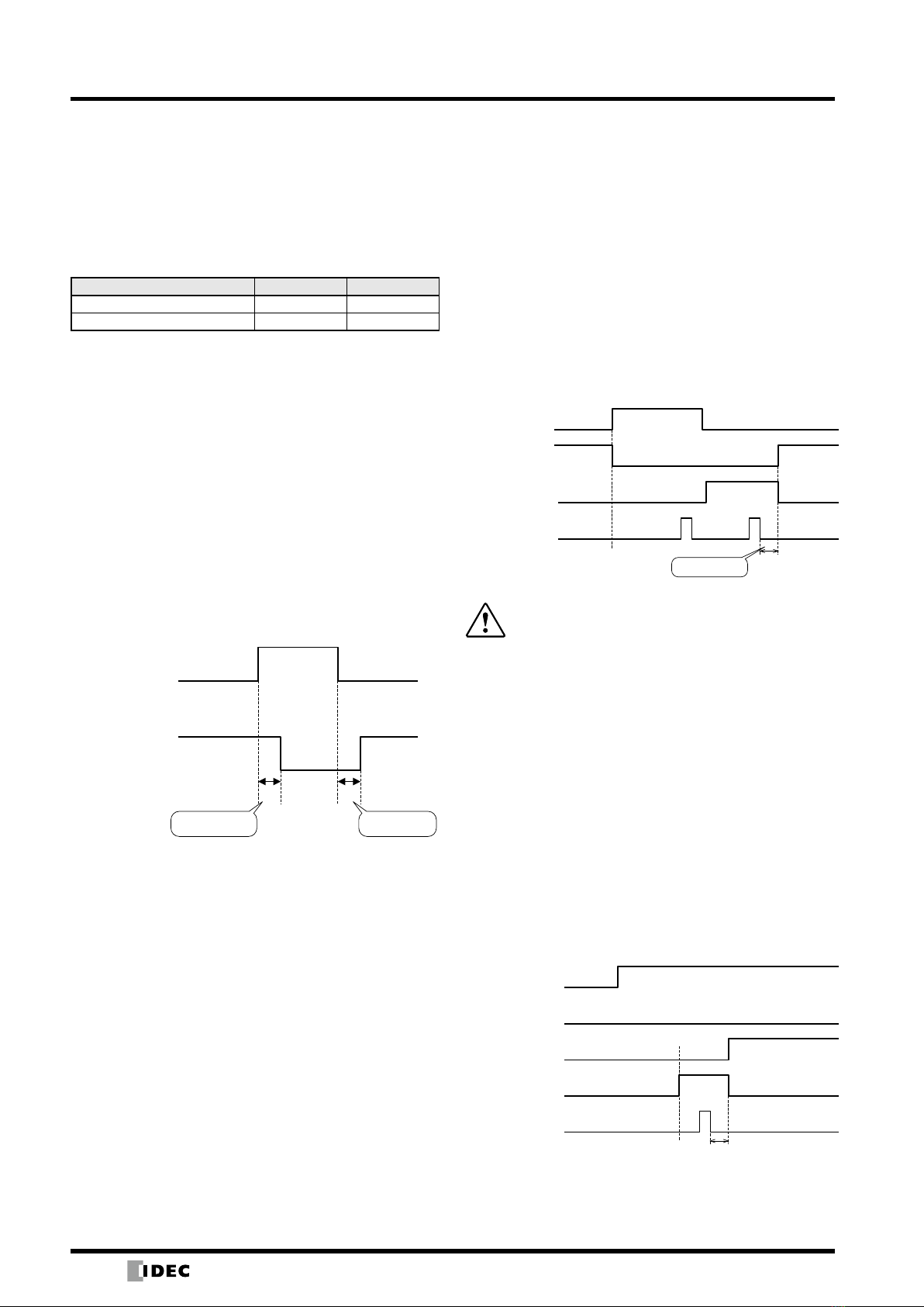
Self-Diagnosis Function of the OSSD
The self-diagnosis function of the OSSD detects
abnormality by switching OSSD 1 to OSSD 2 at intervals
of 300 µs maximum. Therefore, a safety relay or converter
must not respond to this self-diagnosis function.
Time chart
30ms
300μs
300μs
OSSD1
OSSD2
OSSD Signal and Condition of SE1L
The OSSD signal will switch to OFF (0V) when an object
enters a protection zone or when a error is detected by the
self-diagnosis function. By observing the READY signal
and ERR signal with OSSD signal, the operator is able to
recognize the condition of the SE1L. Below shows the
start-up status and operating status between the OSSD,
READY, and ERR signals.
Relationship between OSSD, READY, and ERR signals
Item
Status
Self-
Diagnosis
Function
Object Interlock
Configuration
Signal
OSSD READY*2ERR*3
Start-up
Status
OK − − OFF OFF OFF
FAIL − − OFF OFF OFF
Operating
Status
OK
YES Disabled OFF ON ON
Enabled OFF OFF ON
NO Disabled ON ON ON
Enabled OFF/ON*4ON/OFF*4ON
FAIL*1
YES Disabled OFF ON OFF
Enabled OFF OFF OFF
NO Disabled OFF ON OFF
Enabled OFF OFF OFF
Lockout FAIL − Disabled OFF OFF OFF
− Enabled OFF OFF OFF
*1:The SE1L will switch to a lockout state when a failure occurs
during self-diagnosis.
*2:When the interlock is enabled, the READY signal will change to
a lockout state.
*3:When the ERR signal is congured.
*4:When the conguration of start/restart is set to manual/manual,
the OSSD is OFF and READY is ON. When set to manual/auto,
OSSD is ON, and READY is OFF.
xA non-safety signal is the output from the
warning zone.
xDo not use the warning zone output signal to
control machines or AGVs for safety purposes.
Note:
xWARNING signal is a non-safety signal.
xWarning signals 1 and 2 are not related to the OSSD signal.
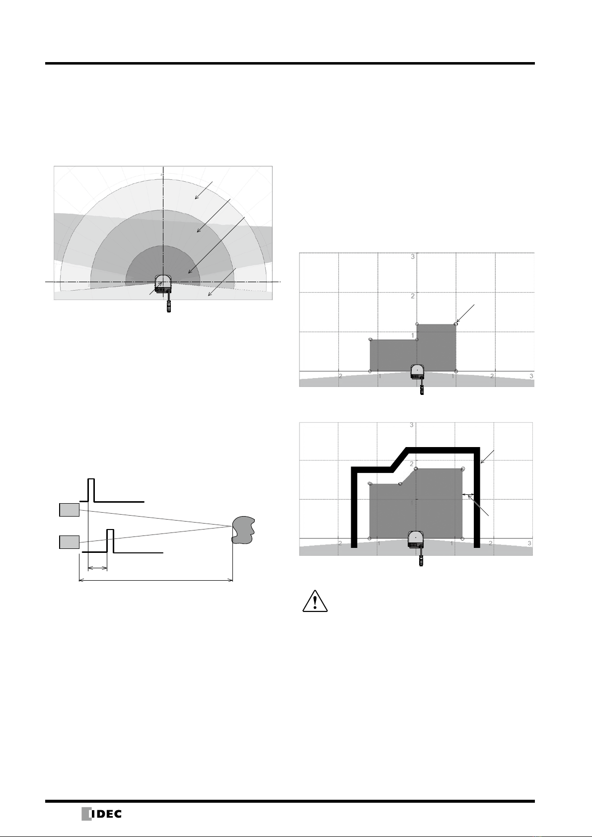
Area Switching
The SE1L can store up to 16 area patterns. Each area
consists of a protection zone, warning zone 1, and
warning zone 2. To switch areas, an external input signal
is required. Table below shows the combinations of input
signals for switching areas.
The number of the current area is displayed on the
7-segment display of the SE1L. The switching time of
areas can be configured.
Area switching combinations
Area
Pattern IN_A IN_B IN_C IN_D IN_A IN_B IN_C IN_D
1 ON ON ON ON OFF OFF OFF OFF
2 OFF ON ON ON ON OFF OFF OFF
3 ON OFF ON ON OFF ON OFF OFF
4 OFF OFF ON ON ON ON OFF OFF
5 ON ON OFF ON OFF OFF ON OFF
6 OFF ON OFF ON ON OFF ON OFF
7 ON OFF OFF ON OFF ON ON OFF
8 OFF OFF OFF ON ON ON ON OFF
9 ON ON ON OFF OFF OFF OFF ON
10 OFF ON ON OFF ON OFF OFF ON
11 ON OFF ON OFF OFF ON OFF ON
12 OFF OFF ON OFF ON ON OFF ON
13 ON ON OFF OFF OFF OFF ON ON
14 OFF ON OFF OFF ON OFF ON ON
15 ON OFF OFF OFF OFF ON ON ON
16 OFF OFF OFF OFF ON ON ON ON
xSee the user’s manual for details.