ICPDAS I-7550 Manual de usuario

i-7550 PROFIBUS to RS-232/422/485 Converter User Manual (Version 1.60) PAGE:1
I-7550 PROFIBUS to RS-232/422/485 Converter
User's Manual
High Quality, Industrial Data Acquisition, and Control Products

i-7550 PROFIBUS to RS-232/422/485 Converter User Manual (Version 1.60) PAGE:2
Warranty
All products manufactured by ICP DAS are under warranty regarding
defective materials for a period of one year from the date of delivery to the
original purchaser.
Warning
ICP DAS assumes no liability for damages resulting from the use of
this product. ICP DAS reserves the right to change this manual at any time
without notice. The information furnished by ICP DAS is believed to be
accurate and reliable. However, no responsibility is assumed by ICP DAS
for its use, or for any infringements of patents or other right of third parties
resulting from its use.
Copyright
Copyright by ICP DAS. All rights are reserved.
Trademark
The names used for identification only may be registered trademarks
of their respective companies.
List of Revision
Date Author Version Revision
2012/04/03 Raiden 1.60 Release

i-7550 PROFIBUS to RS-232/422/485 Converter User Manual (Version 1.60) PAGE:3
Table of Contents
1. Introduction…………………………………………………………... 4
1.1 Features…………………………………………………………. 4
1.2 Specification……………………………………………………..5
2. Hardware……………………………………………………………... 6
2.1 Block Diagram of the I-7550…………………………………… 6
2.2 Pin Assignment…………………………………………………. 6
2.3 Wiring and Jumper Setting Instructions…………………………8
2.4 Setting the PROFIBUS Address……………………………... 14
2.5 LED status indicator……………………………………………15
3. Communication……………………………………………………... 17
3.1 Field of application……………………………………………. 17
3.2 Communication Sequence…………………………………….. 18
3.3 I-7550 in a RS232/422/485 network…………………………... 21
3.4 PROFIBUS I/O Data Area…………………………………… 22
3.5 Communication parameters…………………………………… 28
3.6 Diagnostic messages……………………………………………37
3.7 Establishing Connection with the I-7550………………………38
4. Data Exchange Example……………………………………………. 41
4.1 Configuration………………………………………………….. 41
4.2 Communication Testing………………………………………. 45
5. Troubleshooting…………………………………………………….. 53
6. Dimensions…………………………………………………………. 54

i-7550 PROFIBUS to RS-232/422/485 Converter User Manual (Version 1.60) PAGE:4
1. Introduction
PROFIBUS is a field bus communication system with a wide range of applications,
particularly in the fields of factory and process automation. The I-7550 integrates
devices with serial RS-232, RS-485 or RS-422 interfaces into a PROFIBUS DP
network. Serial I/O devices, electronic scales, operator terminals, barcode readers and
other automation devices can easily be connected to an existing PROFIBUS network.
Figure 1 shows an application example for the I-7550 module.
Figure 1: Application architecture of the I-7550 modules
1.1 Features
●16-Bit Microprocessor inside with 80MHz
●Siemens SPC3 PROFIBUS controller
●Supports PROFIBUS DP-V0 slave
●PROFIBUS transmission rate detect automatically
●Max transmission speed up to 12M bps for PROFIBUS and 115.2K bps for
COM Port
●COM Port driver has 100 KB QUEUE input buffer & 100 KB QUEUE output

i-7550 PROFIBUS to RS-232/422/485 Converter User Manual (Version 1.60) PAGE:5
buffer
●Max length of in/output data is 128 Bytes
●Built-in self-tuner ASIC controller on RS-422/485 port
●2500Vrms High Speed iCoupler Isolation Protection for PROFIBUS network
●3000VDC Isolation Protection on the PROFIBUS side
● Provide LED indicators
● Built-in Watchdog
●Mountable on DIN Rail
1.2 Specification
COM Port specs:
●Serial port - RS-232/RS-422/RS-485
●Serial port interface: 14-pin screw terminal block
●Baud Rate:1200/2400/4800/9600/19200/38400/57600/115200 bps
●Data Format: 7/8 data bits, None/Odd/Even parity bit, 1 stop bit
PROFIBUS specs:
●PROFIBUS interface connector: D-sub 9-pin female
●Baud Rate: 9.6K/19.2K/45.45K/93.75K/187.5K/500K/1.5M/3M/6M/ 12Mbps
●Address Setting: 0~126 (set by DIP switch or EEPROM)
Power requirement:
●Unregulated +10V ~ +30V DC
●Power reverse protection, Over-Voltage brown-out protection
●Power consumption 2.5W
Module specs:
●Dimensions: 119mm X 72mm X 33mm
●Operating temperature: -25 ~ 75 ºC
●Storage temperature: -30 ~ 85 ºC
● Humidity:5 ~ 95%, non-condensing
● LED Status Indicators (Table 1)
Table 1: LED status indicator
PWR LED −Shows the power state
−COM Port state: transmit or receive data
ERR LED −Show error state
RUN LED −Show communication state of PROFIBUS

i-7550 PROFIBUS to RS-232/422/485 Converter User Manual (Version 1.60) PAGE:6
2. Hardware
2.1 Block Diagram of the I-7550
Figure 2: Block diagram of the I-7550
2.2 Pin Assignment
Figure 3: Pin assignment of the I-7550
RS-485
DRIVE

i-7550 PROFIBUS to RS-232/422/485 Converter User Manual (Version 1.60) PAGE:7
Table 2: 14-pin screw terminal block
Pin Name Description
1 D+ Data+ of RS-485
2 D- Data- of RS-485
3 - N/A
4 TX+ Transmit Data+ of RS-422
5 TX- Transmit Data- of RS-422
6 RX+ Receive Data+ of RS-422
7 RX- Receive Data- of RS-422
8 - N/A
9 RX Receive Data of RS-232
10 TX Transmit Data of RS-232
11 GND GND of RS-232
12 - N/A
13 +VS V+ of Power Supply(+10 to +30VDC)
14 GND GND of Power Supply
Table 3: PROFIBUS DB9 Female Connector
Pin Name Description
1 - N/A
2 - N/A
3 B Non-inverting Bus Line
4 ISODE Isolated DE output for use in PROFIBUS
applications where the state of the isolated drive
enable node needs to be monitored.
5 GND Power supply ground for the first node and the last
node
6 VP +5V Power Supply for the first node and the last
node
7 - N/A
8 A Inverting Bus Line
9 - N/A

i-7550 PROFIBUS to RS-232/422/485 Converter User Manual (Version 1.60) PAGE:8
2.3 Wiring and Jumper Setting Instructions
The I-7550 module supports PROFIBUS to Serial Port communication. It is
recommended to use only one serial port (RS232, RS485 or RS422) of the converter
at the same time. The following section describes the necessary steps to be taken to
connect one of the three COM port types to a serial device or serial network.
2.3.1 RS-232 Connection
The RS-232 port of the I-7550 has got three pins. The wiring of the RS-232
device with the RS232 port of the I-7550 is shown in Figure 4.
Figure 4: RS-232 wiring diagram
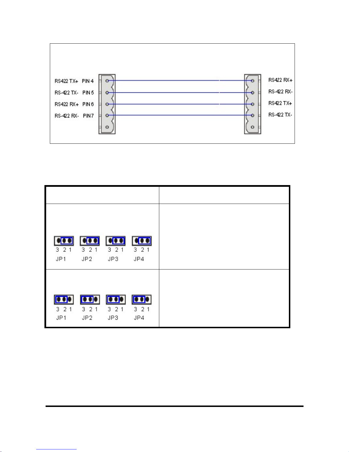
2.3.2 RS-422 Connection
The RS-422 wiring connection is shown in Figure 5.
The I-7550 converter is always a PROFIBUS slave but it can in a local RS-422
network either take the position of a master or that of a slave. Depending on
whether the converter acts as a local master or as a slave and on the number of
devices connected to the RS-422 network device the four jumpers provided by
the module has to be set according to Table 4. The jumpers set the pull high and
pull down resistors for the RS-422 port (Figure 6, Figure 7).
i-7550
RS-232 COM
p
ort RS-232 device
i-7550 PROFIBUS to RS-232/422/485 Converter User Manual (Version 1.60) PAGE:9
Figure 5: RS-422 connection
Table 4: Jumper position for the RS-422 port
Pull high/low resistor Condition
Enabled
(default) −The I-7550 is the master in RS-422
bus or
−the number of devices connected to
the RS-422 bus is less than 10
Disabled −The I-7550 is a slave in RS-422 bus
or
−the number of devices connected to
the RS-422 bus exceeds 10
RS-422 device
i-7550
RS-422
p
or
t

i-7550 PROFIBUS to RS-232/422/485 Converter User Manual (Version 1.60) PAGE:10
Figure 6: Configuration of pull high/low resistor for the RS-422 port
Figure 7: The positions of pull high/low resistors in I-7550 module
2.3.3 RS-485 Connection
The RS-485 wiring diagram is shown in Figure 8.
The I-7550 converter can only act in the PROFIBUS network as a slave. In a RS-
Tabla de contenidos
Otros manuales de Convertidor de medios de ICPDAS


