Ice-O-Matic RGA0501-HM Manual de usuario
Ice‐o‐Matic®
11100East45
th
Ave
Denver,Colorado80239
PartNumber9081487‐01Rev.K
INSTALLATION MANUAL REMOTE CONDENSERS
RCA1001, RCA1061,
RCA2061, RCA3061, RCA3561
RGA0501-HM, RGA1061-HM

Introduction
Ice-O-Matic® provides this manual as an aid to the service technician in installation and
maintenance of remote condensers. Do not attempt to perform installation, start-up or
maintenance unless you have read and fully understand this manual.
For a Service Provider, please reference our “Service and Support” tab at www.iceomatic.com
Keep this manual for future reference.
The Remote Condenser Service Parts Manuals are available separately.
Ice-O-Matic® icemakers and dispensers are not approved for outdoor installation.
WARNING: Always disconnect electrical power whenever maintenance or repairs are
performed on the remote condenser and related equipment.
CAUTION: Always wear protective eyewear whenever maintenance or repairs are
performed on the remote condenser and related equipment.
Ice-O-Matic® Warranty
Every Ice-O-Matic® remote condenser is backed by a warranty that provides both parts and
labor coverage. Ice-O-Matic® warranty registration should be filed online at
www.iceomatic/warranty

Freight Claims Procedure
Inspect Promptly
This merchandise has been carefully inspected and packed in accordance with the carrier’s
packing specifications. Responsibility for safe delivery has been assumed by the carrier. If loss
or damage occurs, you as the consignee must file a claim with the carrier and hold the container
for carrier’s inspection.
Visible Loss or Damage
Any external evidence of loss or damage must be fully described and noted on your freight bill
or express receipt and signed by the carrier’s agent. The claim should be filed on a form
available from the carrier.
Concealed Loss or Damage
If loss or damage does not appear until merchandise has been unpacked, make a written
request for inspection by the carrier within 5 days of the delivery date. Then file a claim on a
form from the carrier.
File Claim without Delay
Do Not Return Damaged Merchandise to Ice-O-Matic®

Table of Contents
General Information Page 1
Condenser and Ice Machine Pairing Page2
Installation Page 5
Remote Refrigeration System Page 7
Component Description Page 8
Electrical Connections Page 9
Condenser Leg Installation Page10
Refrigeration Tube Routing Page11/12
Coupling Instructions Page13
1
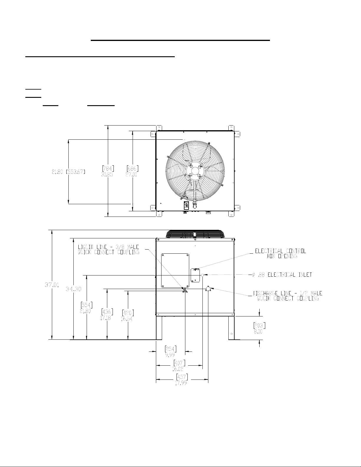
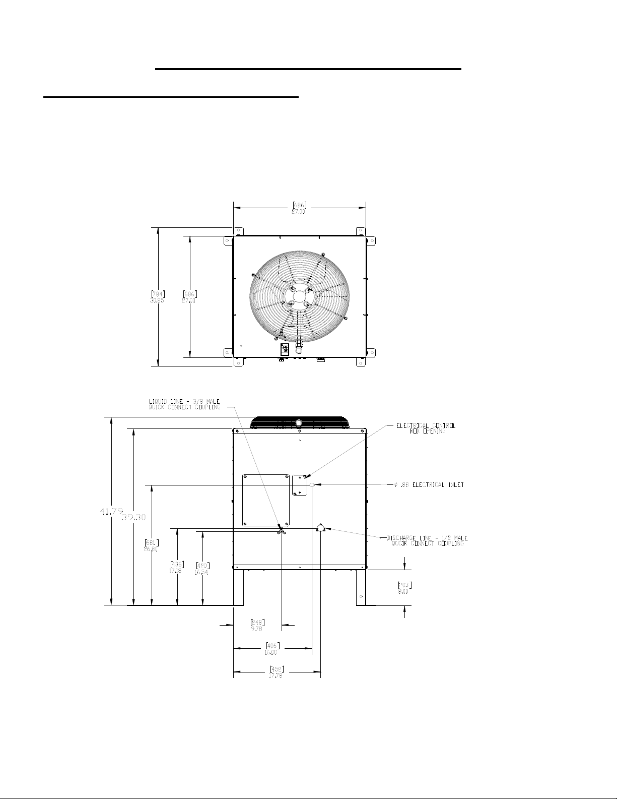
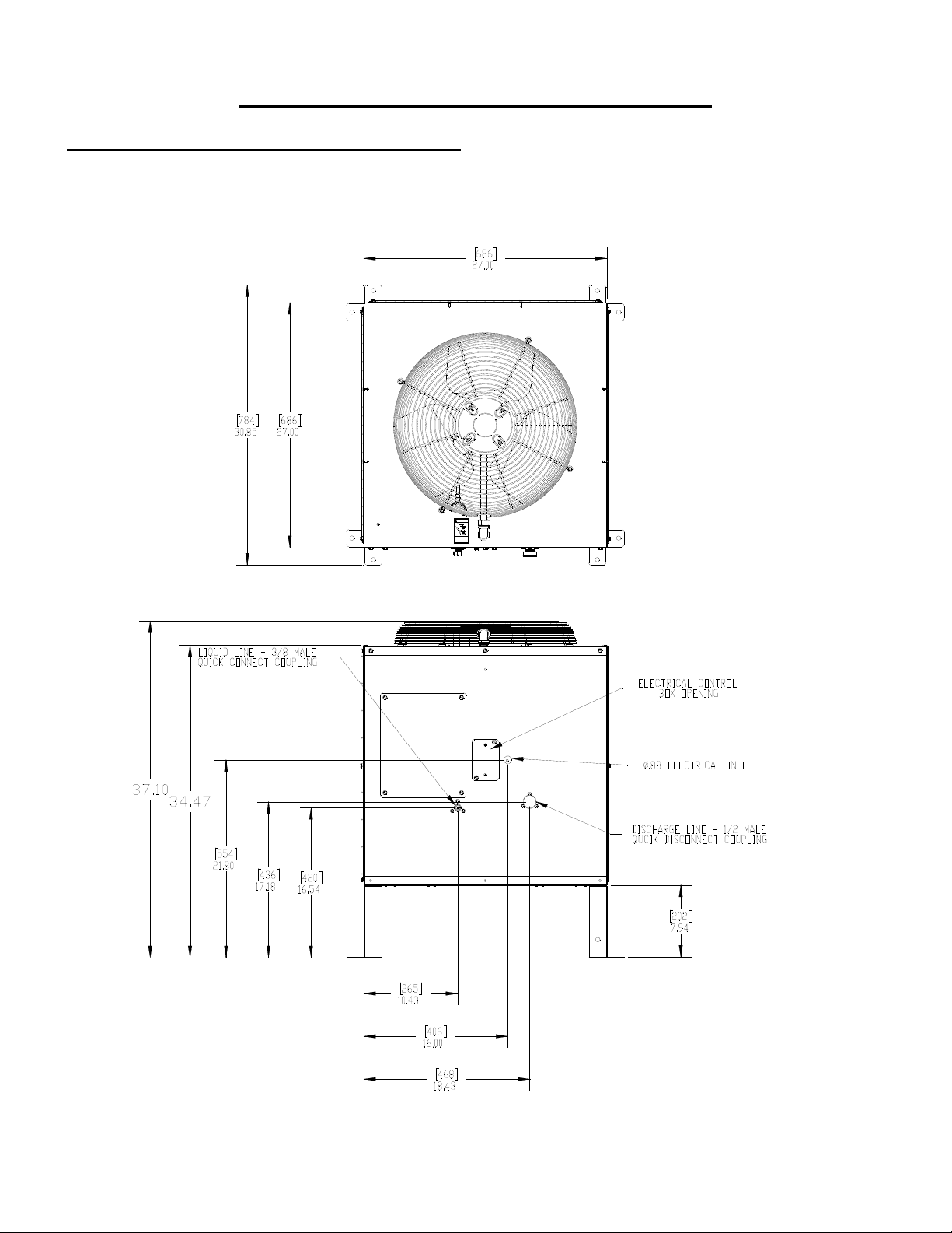
Condenser Dimensions (Inches)
Model Length Width Height Grill Kit Field Installed
RCA1001 30.85 30.85 37.01 GRILL10
RCA1061 30.85 30.85 37.01 GRILL10
RCA2061 30.85 30.85 41.79 GRILL20
RCA3061 30.85 30.85 37.10 GRILL30
RCA3561 30.85 30.85 41.79 GRILL20
RGA0501-HM* 30.85 30.85 37.01 GRILL10
RGA1061-HM* 30.85 30.85 37.01 GRILL10
*The RGA models DO NOT have a Mixing Valve in the condenser.
The RCA and RGA models DO NOT include side grills, they can be ordered as a Field Install
Kit, See Specific Model Number for Kit Part Number
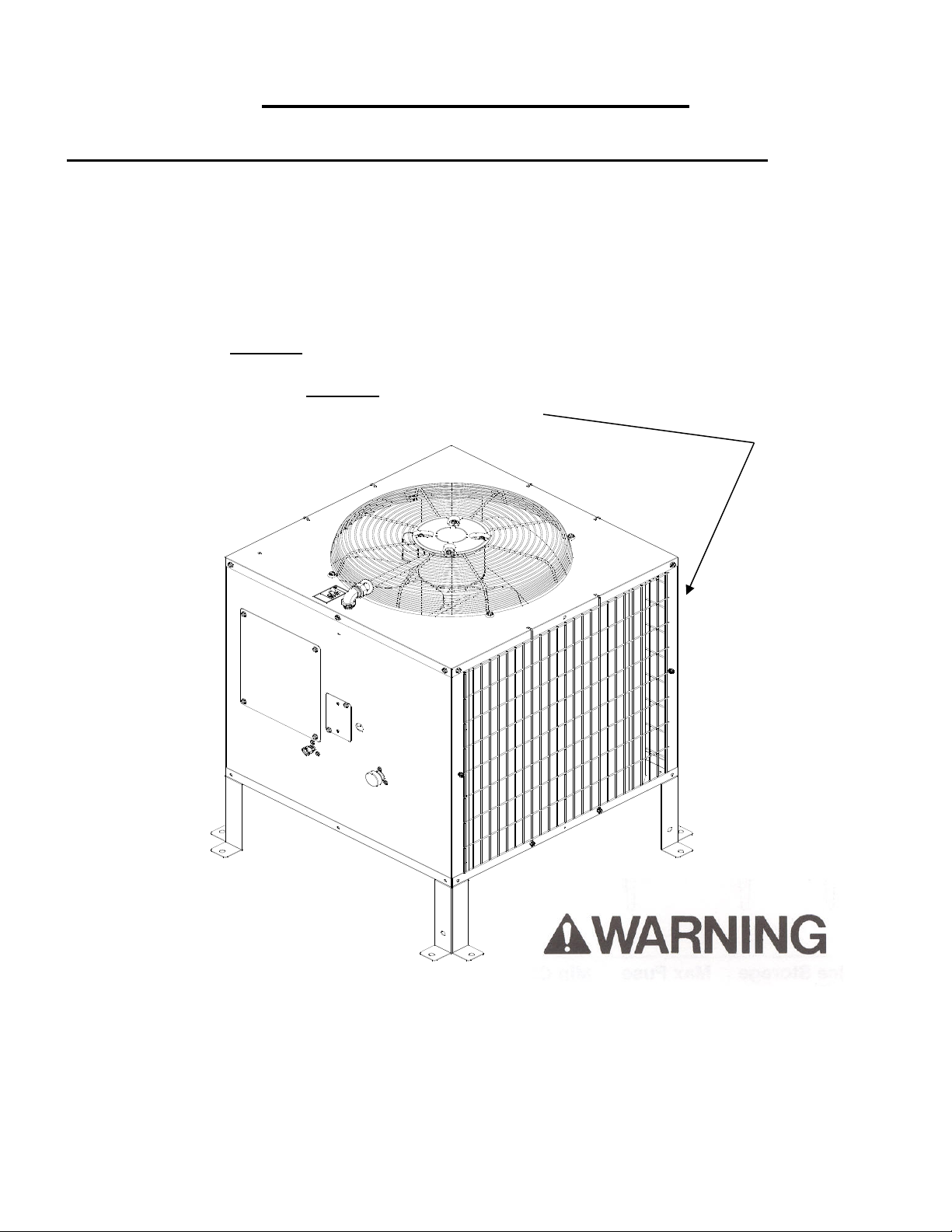
Note the warning symbol where it appears in this manual. It is an alert for important safety
information on a hazard that might cause serious injury. Keep this manual for future
reference.
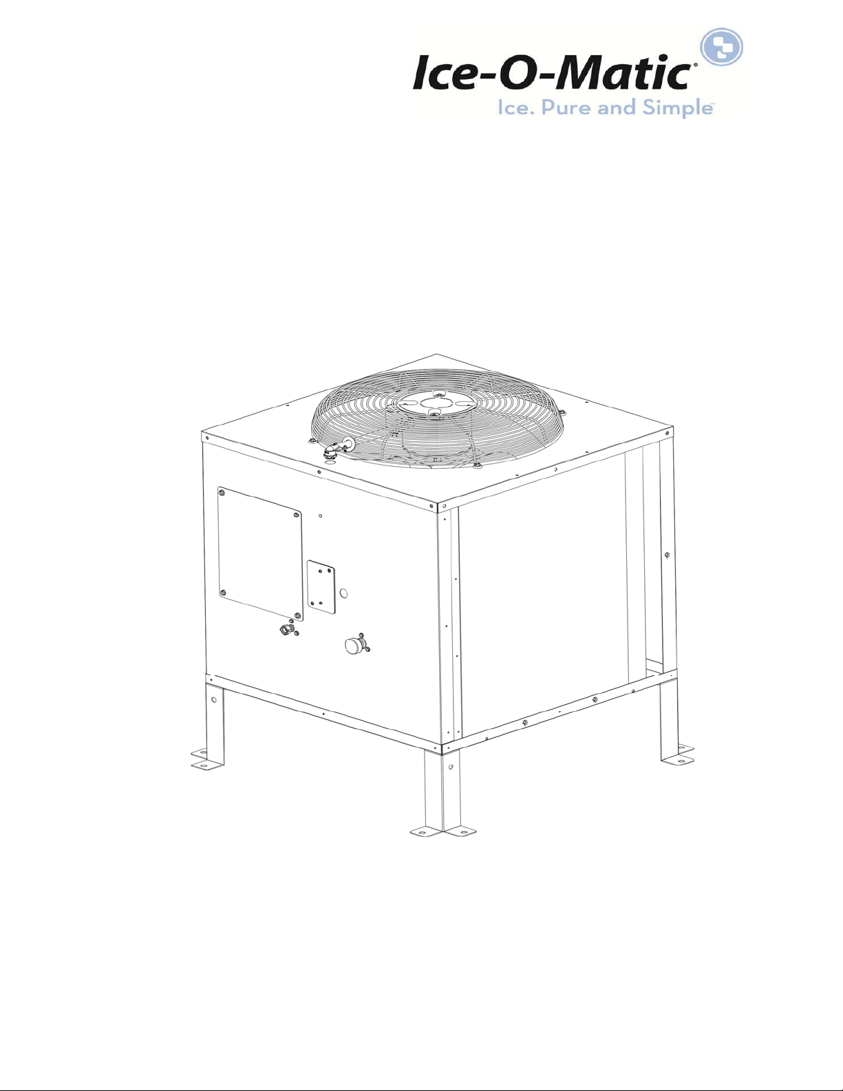
RCA Condenser
RGA Condenser
2
Condenser and Ice Machine Pairing
Remote Condenser Ice Machine Model
RCA1001 CIM0530R
RCA1061 CIM0535R, CIM0636R
RGA0501-HM* GEM0650R, MFI0800R
RGA1061-HM* GEM0956R, GEM1306R, MFI1256R, MFI1506R
*The RGA models DO NOT have a Mixing Valve in the condenser
3
Condenser and Ice Machine Pairing
Remote Condenser Ice Machine Model
RCA2061 CIM0825R, CIM0826R, CIM0835R,CIM0836R,CIM0837R,CIM1125R,
CIM1126R,CIM1135R, CIM1136R, CIM1137R, GEM2006R, MFI2306R,
CIM1446R, CIM1447R
RCA3561 CIM2046R, CIM2047R
4
Condenser and Ice Machine Pairing
Remote Condenser Ice Machine Model
RCA3061 CIM1845R, CIM1545R
5
Installation
Ice-O-Matic® Remote Condenser Systems are comprised of three components. The pre-charged remote
condenser, the pre-charged ice maker and the pre-charged line set. The pre-charged line sets are available
in 25, 40, or 75 foot line set lengths.
Note: The 75 foot line set will require adding an additional 28 ounces of refrigerant.
Normal installation of the ice maker should be followed. Reference the installation instructions included with
the ice maker. In any installation, the pre-charged line sets, consisting of a liquid line (3/8” dia.) and a
discharge line (1/2” dia.) are used as a one-time initial charge type installation.
Once the sealed couplings are connected and the internal seal is broken, the lines cannot be disconnected
without losing the refrigerant charge. They are, however, reusable and when the couplers are removed and
reconnected, the complete refrigeration system must be evacuated and re-charged with the proper amount
of refrigerant. Reference the ice maker data plate or ice maker service manual for proper refrigerant
charge.
General Description
The remote condenser should not be used in areas where sufficient airflow is not available, in the area the
ice maker is being installed, or the heat being rejected by the condenser coil will be undesirable.
The condenser coil should not be exposed to temperatures below -20F (-29C) or above 120F (49C).The
remote condenser functions as a normal refrigeration system until the temperature at the condenser coil
drops below 70F. At this time the mixing valve will begin to bypass enough hot gas from the discharge line
directly into the receiver to keep the liquid line feeding the expansion valve at a steady pressure. The
amount of gas bypassed will depend on the temperature at the condenser coil (the colder the temperature
at the condenser coil, the more gas will bypass and the tubing between the mixing valve and receiver will
become warmer).
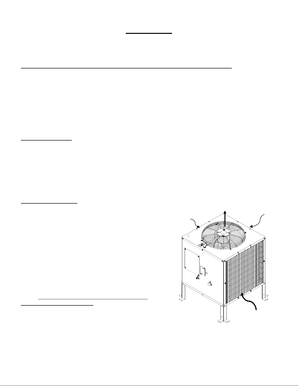
Condenser LocationWhen choosing a location for the remote condenser, reference the following
guidelines:
1. Choose a location that is protected from extremes of dirt,
dust, rain, sun and prevailing winds.
2. Vertical air discharge mounting of the condenser is
required with at least 48 inch clearance above the
condenser.
3. Condenser should be mounted higher than the ice
machine.
4. Condenser must be level.
5. Condenser should not be exposed to temperatures below
-20F or above 120F.
6. Installation must meet all local and national building,
plumbing and electrical codes.
7. The condenser must have a minimum clearance of
18 inches around all 4 sides.
8. Install condenser with the included legs or other elevated
mounting solution. There should be clearance between
the bottom of the condenser and the surface on which it is
mounted.
Airflow In
Airflow In
Airflow In
Airfl
o
w
Out
6
The RCA remote condensers incorporate the mixing valve in the condenser. This configuration allows up to
a 100 foot calculated remote line set run.
The RGA remote condensers Do Not have a mixing valve in the condenser.
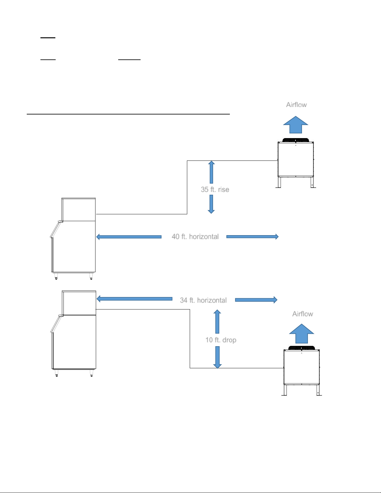
Maximum Rise is 35 feet
Maximum Drop is 10 feet.
Maximum equivalent run is 100 feet.
Formula for calculating maximum equivalent run is as follows:
Rise x 1.7 + Drop x 6.6 + horizontal run = equivalent run
Example: 35 ft. rise x 1.7 + 40 ft. horizontal = 99.5 ft. equivalent line run
Example: 10 ft. drop x 6.6 + 34 ft. horizontal = 100 ft. equivalent line run
A
irflow
Airflow
35 ft. rise
40 ft. horizontal
10 ft. drop
34 ft. horizontal
Este manual sirve para los siguientes modelos
6
Tabla de contenidos
Otros manuales de Bomba de calor de Ice-O-Matic


Manuales populares de Bomba de calor de otras marcas


Mitsubishi Electric
Mitsubishi Electric PUZ-SWM60VAA Manual de usuario

Dimplex
Dimplex LI 16I-TUR Guía del usuario

Carrier
Carrier WSHP Open v3 Guía de configuración rápida

TGM
TGM CTV14CN018A Manual de usuario

Carrier
Carrier 38MGQ Series Manual de usuario

Kokido
Kokido K2O K880BX/EU Guía de solución de problemas

Viessmann
Viessmann VITOCAL 300-G PRO Type BW 2150 Guía rápida

Carrier
Carrier 48EZN Manual de usuario

Viessmann
Viessmann KWT Vitocal 350-G Pro Series Instrucciones de funcionamiento

Ariston
Ariston NIMBUS Manual de usuario

Weishaupt
Weishaupt WWP L 7 Guía del usuario

GE
GE Zoneline AZ85H09EAC Manual de usuario